
If you have ever wondered what does a potentiometer do when you turn the volume knob on an amplifier or adjust the dimmer on a desk lamp, you are asking about one of the most fundamental electromechanical components in electronics. At its core, a potentiometer (often shortened to "pot") is a three-terminal resistor with a sliding or rotating contact that forms an adjustable voltage divider. However, reading a textbook definition rarely helps when you are staring at a breadboard. In this project-based guide, we will explore the practical function of potentiometers by wiring them into real circuits, analyzing their physical construction, and troubleshooting common failure modes.
The Core Question: What Does a Potentiometer Do in a Circuit?
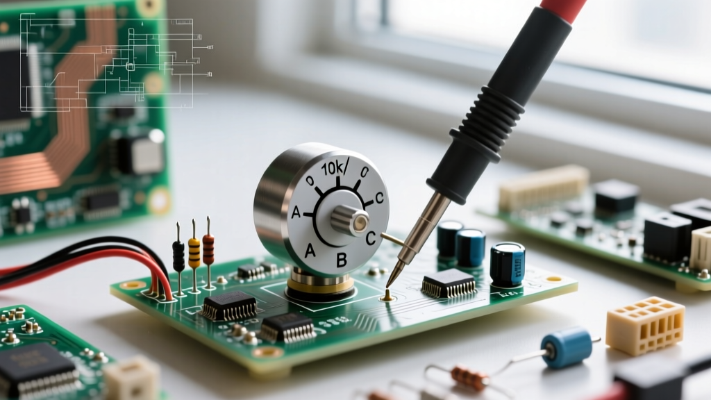
To understand what a potentiometer does, you must look inside the casing. A standard 9mm carbon track potentiometer consists of a resistive element (the track) and a wiper (the slider). The two outer pins are connected to the ends of the resistive track, while the middle pin is connected to the wiper. As you turn the shaft, the wiper moves along the track, changing the resistance between the middle pin and the outer pins. This mechanical-to-electrical translation allows you to manually control voltage or current in real-time. According to the foundational texts at All About Circuits, the potentiometer's ability to divide voltage makes it indispensable for sensor calibration and user interfaces.
Project 1: Dimming an LED (The Rheostat Configuration)
The simplest way to answer "what does a potentiometer do" is to use it as a variable resistor, also known as a rheostat. In this configuration, you only use two of the three pins: one outer pin and the middle wiper pin. As you turn the knob, the total resistance of the component changes, directly restricting or allowing current flow.
Building the Circuit and Component Selection
For this project, you will need a standard 5mm LED, a 220Ω current-limiting resistor, and a B10K (10,000 ohm, linear taper) potentiometer. Wire the 5V supply to one outer pin of the pot, connect the wiper (middle pin) to the anode of the LED, and place the 220Ω resistor between the LED cathode and ground.
Critical Design Rule: Never wire a potentiometer directly across a power supply without a series load resistor. If you turn the pot to 0Ω without a load resistor, you will create a dead short, potentially destroying your power supply or melting the carbon track inside a standard 0.5W pot. For high-current applications like DC motor speed control, standard carbon pots will burn out. Instead, you must select a wirewound potentiometer rated for at least 2W to 5W, such as the Vishay 534B1 series.
Project 2: Reading Analog Sensors with a Microcontroller
While the rheostat configuration controls current, the true power of a potentiometer lies in its three-terminal voltage divider configuration. This is how microcontrollers like the Arduino read analog user inputs.
The Voltage Divider Math
Wire the left outer pin to Ground (0V), the right outer pin to 5V, and the middle wiper pin to the Arduino's A0 analog input. As detailed in the SparkFun Voltage Divider Tutorial, the output voltage at the wiper is determined by the formula: Vout = Vin × (R2 / (R1 + R2)). By turning the knob, you smoothly sweep the voltage at the wiper from 0V to 5V.
int potPin = A0;
int ledPin = 9;

void setup() {
  pinMode(ledPin, OUTPUT);
  Serial.begin(9600);
}

void loop() {
  int sensorValue = analogRead(potPin);
  // Map the 10-bit ADC value (0-1023) to an 8-bit PWM value (0-255)
  int pwmValue = map(sensorValue, 0, 1023, 0, 255);
  analogWrite(ledPin, pwmValue);

  Serial.print("Raw ADC: ");
  Serial.println(sensorValue);
  delay(50);
}
When uploading this code, you may notice the serial monitor output jittering slightly even when you are not touching the knob. This is due to the internal resistance of the carbon track and the sample-and-hold capacitor inside the microcontroller's ADC (Analog-to-Digital Converter). To stabilize the reading, solder a 0.1μF ceramic capacitor between the wiper pin and ground. This creates a low-pass filter that smooths out high-frequency electrical noise, a crucial step documented in the Arduino analogRead() documentation.
Linear vs. Audio Taper: Choosing the Right Pot
Not all potentiometers behave the same way when turned. The physical shape of the carbon track dictates the "taper," which defines how resistance changes relative to the shaft angle. Choosing the wrong taper is a common beginner mistake that results in audio volume knobs that do nothing for 80% of the rotation, and then suddenly blast at maximum volume.
| Taper Type | Marking Code | Resistance Curve | Ideal Project Application |
|---|---|---|---|
| Linear | B (e.g., B10K) | Resistance changes at a constant, uniform rate. | LED dimming, motor speed control, Arduino sensor inputs. |
| Logarithmic (Audio) | A (e.g., A10K) | Resistance changes slowly at first, then rapidly. | Audio volume controls (matches human hearing perception). |
| Reverse Log | C (e.g., C10K) | Resistance changes rapidly at first, then slowly. | Specialized audio balance controls, specific synth filters. |
For DIY guitar pedals or synthesizer builds, always reach for Alpha RV24AF series audio taper pots. Using a linear B-taper for a volume knob will make the audio perception feel highly unnatural, as human hearing responds logarithmically to sound pressure levels.
Prototyping Precision: Single-Turn vs. Multi-Turn Trimpots
When building permanent circuits on a PCB, you often need to set a specific threshold voltage that rarely changes, such as the trigger point for a 555 timer or the bias current on a transistor. For this, we use trimpots (trimming potentiometers). A standard single-turn cermet trimpot (like the Bourns 3386P) costs around $0.50 and allows for quick adjustments. However, achieving a precise voltage like 2.547V is incredibly frustrating on a single-turn pot, as a millimeter of finger movement shifts the voltage by tens of millivolts.
For precision calibration, use a multi-turn trimpot, such as the Bourns 3296W (25-turn). These cost slightly more (around $3.50) and require a small flathead screwdriver. The internal lead screw mechanism forces the wiper to move only a fraction of a millimeter per full rotation of the screw, granting you micro-adjustment capabilities essential for calibrating lab equipment or precision sensor bridges.
Real-World Failure Modes and Troubleshooting
Understanding what a potentiometer does also requires knowing how they fail. Potentiometers are mechanical components, making them one of the most common points of failure in aging electronics.
- Wiper Oxidation and Crackling: Over time, moisture and dust infiltrate the casing, causing the carbon track to oxidize. When you turn the knob, you hear a "crackling" sound in audio circuits. This is the wiper momentarily losing electrical contact. Fix: Spray a small amount of DeoxIT D-Series contact cleaner into the casing slots and rotate the shaft 20 times to wipe the track clean.
- Thermal Drift: Standard carbon composition pots have a poor temperature coefficient (often ±1000 ppm/°C). If your circuit is placed near a heat source, the baseline resistance will drift, ruining precision measurements. Fix: Swap carbon pots for cermet or conductive plastic elements, which offer vastly superior thermal stability.
- Mechanical Wear: Cheap pots rated for 10,000 rotation cycles will eventually wear a physical groove into the carbon track, leading to permanent dead spots. For heavy-use interfaces (like DJ mixers), always specify conductive plastic potentiometers rated for 1,000,000+ cycles.
By moving beyond the basic definition and applying these components in voltage dividers, rheostat circuits, and precision calibration networks, you transform a simple theoretical question into practical engineering mastery. The next time you design a user interface or sensor array, you will know exactly which taper, material, and wiring topology your project demands.