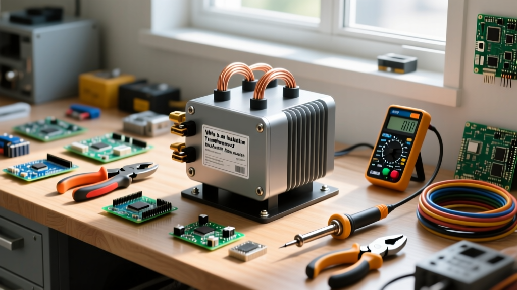

An isolation transformer is a transformer that transfers AC electrical power to a load while galvanically isolating the load from the primary power source, effectively breaking the direct electrical and ground connection. In a real circuit, it changes the safety profile by removing the earth-ground reference from the secondary side, which eliminates ground loops and prevents a single accidental touch to a live chassis from completing a lethal circuit back to the service panel.
The Core Difference: Isolation vs. Autotransformers
Before wiring up your bench, you must understand that not all transformers provide isolation. The most dangerous mistake a hobbyist can make is assuming a variable AC supply (a Variac) is an isolation transformer. It is not. Below is a breakdown of how common bench transformers handle galvanic isolation and shock hazards.
| Transformer Type | Galvanic Isolation? | Winding Configuration | Touching 1 Live Secondary + Earth | Common Application |
|---|---|---|---|---|
| Isolation (1:1) | Yes | Separate Primary & Secondary | No Shock (Circuit Incomplete) | Electronics repair, medical |
| Autotransformer (Variac) | No | Single Tapped Winding | Lethal Shock | Variable AC voltage testing |
| Step-Down Control | Yes | Separate Primary & Secondary | No Shock (Usually) | HVAC control circuits, PLCs |
| Constant Voltage (Ferroresonant) | Yes | Separate + Magnetic Shunt | No Shock | Legacy sensitive IT/medical gear |
Notice the autotransformer row. Because an autotransformer uses a single continuous winding with a sliding tap, the output is physically and electrically connected to the mains input. If your mains neutral is bonded to earth at the panel, the 'neutral' side of your Variac output is still referenced to earth ground. For true bench safety, you need separate primary and secondary windings, as detailed in the All About Circuits guide on isolation transformers.
What an Isolation Transformer Actually Changes in a Circuit
To understand what changes, look at standard mains power. In a typical US 120V outlet, the neutral wire is bonded to the earth ground rod at your service entrance. The 'hot' wire oscillates at 120V RMS relative to that earth ground. If you touch the hot wire while standing on a concrete floor, current flows through your body, into the earth, and back to the utility transformer's ground bond. You complete the circuit.
When you insert a 1:1 isolation transformer between the wall and your device, the secondary winding creates a brand new, localized AC voltage. Crucially, neither side of this secondary winding is bonded to earth ground. The secondary is 'floating'.
Think of a bird sitting on a 10,000V high-tension power line. The bird doesn't get shocked because it is isolated from the ground; there is no path for current to flow through the bird to the earth. Similarly, if you touch one wire on the floating secondary of an isolation transformer, no current flows through you to ground because the circuit is incomplete. The transformer has effectively turned a grounded system into an ungrounded, floating system, a principle heavily relied upon in Fluke's electrical safety guidelines.
Worked Numeric Example: Sizing for an Electronics Repair Bench
Let's say you are troubleshooting a 600W server switch-mode power supply (SMPS) and need to probe the primary-side switching MOSFETs with an oscilloscope. You need to size your isolation transformer correctly to handle both the continuous load and the inrush current.
Load: 600W
Mains Voltage: 120V AC
Required Current: 600W / 120V = 5.0 Amps
If you buy a standard 500VA bench isolation transformer, its maximum continuous current rating is 4.16A (500VA / 120V). Running a 600W load on a 500VA transformer will cause the core to saturate, the windings to overheat, and the internal thermal fuse to trip. You must step up to a 1000VA (1kVA) isolation transformer, which provides 8.33A of continuous headroom (typically costing between $350 and $550 for a benchtop unit like the BK Precision 1651).
The Inrush Gotcha: When you first flip the switch on that SMPS, the 470µF bulk primary capacitor is completely discharged. For the first few milliseconds of the AC cycle, it looks like a dead short. A 1kVA isolation transformer typically has an internal impedance of about 3% to 5%. This internal impedance acts as a natural current limiter, softening the inrush spike and protecting the SMPS bridge rectifier diodes from blowing out—a hidden benefit of using a properly sized, heavy iron-core transformer over a solid-state electronic isolator.
Where You Meet This in Practice
You will encounter isolation transformers in three primary environments, each solving a very specific physical problem:
- Electronics Repair and Oscilloscope Probing: Oscilloscopes have their probe ground clips tied directly to the earth ground pin of their power cord. If you clip that ground to the 'hot' side of a bridge rectifier in a live SMPS, you create a dead short through the scope. By powering the SMPS through an isolation transformer, the circuit floats, and you can safely clip your scope ground anywhere on the primary side without exploding components or tripping your bench GFCI.
- Medical Patient Care Vicinities: In hospitals, NFPA 99 (Health Care Facilities Code) mandates isolated power systems in wet procedure locations (like operating rooms). If a piece of medical equipment develops an internal ground fault, an isolated system prevents the chassis from becoming energized relative to the patient, preventing micro-shock hazards that could induce cardiac fibrillation.
- Marine Shore Power: When a boat plugs into dockside AC power, the boat's grounding system becomes tied to the marina's ground. This can create galvanic corrosion cells, rapidly eating away at the boat's underwater metals and sacrificial zinc anodes. Marine isolation transformers pass the AC power while blocking the DC galvanic current path, saving the hull.
- Audio and Studio Gear: Ground loops occur when two pieces of audio equipment are connected by a signal cable and also plugged into different wall outlets with slightly different ground potentials. This causes a 60Hz hum. Running the gear through an isolation transformer (or using audio-specific signal isolators) breaks the loop.
Common Confusions and Bench Mistakes
Even experienced makers trip up on the nuances of isolated power. Here are the most common errors to avoid on your workbench:
Confusing GFCI with Isolation: A Ground Fault Circuit Interrupter (GFCI) measures the current imbalance between hot and neutral and trips if 5mA leaks to ground. It does not isolate the circuit. If you touch the hot wire and ground, the GFCI will let you take the full shock for up to 20 milliseconds before tripling—enough time to cause severe injury or lock your muscles to the conductor. An isolation transformer prevents the shock from happening in the first place by ensuring no current can flow to ground.
Defeating the Isolation by Grounding the Secondary: Sometimes, a technician will bond one leg of the isolation transformer's secondary output to earth ground to stabilize a floating measurement. The moment you make that bond, the secondary is no longer isolated. It reverts to a standard grounded system, and touching the remaining 'hot' leg will shock you. Always verify your secondary is floating with a multimeter (measuring >100k ohms between either secondary leg and earth ground) before probing.
Overlooking the VA Rating for Motor Loads: If you are using an isolation transformer to test an AC induction motor or a compressor, the locked-rotor inrush current can be 6 to 8 times the running current. A 500VA transformer will violently sag its output voltage and trip its breaker when hit with a 3A motor's startup spike. For inductive motor loads, always size the isolation transformer at least 2.5 times the motor's running VA rating.