
Voltage is the electrical potential difference that pushes charge through a circuit, while current is the actual rate of flow of that electrical charge. When you ask "what is the current and voltage" in a specific circuit, you are really asking how much electromotive "push" is available from the source, and how much "flow" the connected load will demand based on its resistance. Understanding this relationship is the absolute bedrock of electrical design, dictating everything from the wire gauge you pull through conduit to the breaker size you install in a panel.
The Core Difference: Potential vs. Flow
To separate these two concepts, it helps to look at their behavior in an open circuit. Voltage exists even when no current is flowing. A standard 9V battery sitting on your workbench has 9 volts of potential difference between its terminals, but zero current is moving because the circuit is open. Current only exists when a closed loop allows charge to move from a higher potential to a lower potential.
In electrical terms, voltage is measured in Volts (V) and represents the work needed to move a unit of charge between two points. Current is measured in Amperes (A) and represents one Coulomb of charge passing a point per second. According to Ohm's Law, they are bound together by resistance (R): I = V / R.
A common point of confusion is assuming a power supply "pushes" its rated current into a load. A 12V 10A power supply does not force 10 amps into every device you plug into it. The 10A rating is simply the maximum capacity the supply can provide before it overheats or shuts down. The actual current drawn is determined entirely by the load's resistance. If you connect a 12V LED strip that only requires 2A, the supply will happily provide exactly 2A.
Real-World Values: Common Voltages and Current Limits
Abstract theory only gets you so far. When you are designing a system or troubleshooting a fault, you need to know the nominal values, the acceptable real-world tolerances, and the physical limits of the conductors carrying the power. The table below outlines standard systems you will encounter on the bench and in the field.
| System Type | Nominal Voltage | Acceptable Measured Range | Typical Max Continuous Current | Minimum Copper Wire Size (AWG) |
|---|---|---|---|---|
| USB-C PD (Device Charging) | 20V DC | 19.0V - 21.0V | 5A | 20 AWG (Internal cable) |
| 12V Automotive / LED Strips | 12V DC | 11.5V - 14.4V | 15A | 14 AWG (Chassis wiring) |
| US Residential 120V Mains | 120V AC (RMS) | 114V - 126V | 15A or 20A | 14 AWG or 12 AWG (NM-B) |
| US Residential 240V Mains | 240V AC (RMS) | 228V - 252V | 30A | 10 AWG (NM-B) |
| 48V Telecom / Solar Battery | 48V DC | 42.0V - 58.4V | 60A+ | 6 AWG or 4 AWG (THHN) |
Reading the Table: The "Acceptable Measured Range" for AC mains is based on the ANSI C84.1 standard, which dictates that utility delivery should stay within ±5% of nominal at the service entrance. For DC systems like 12V automotive, a resting battery reads ~12.6V, but an alternator charging the system will push it to 14.4V. Your components must be rated to handle the upper limit, not just the nominal number.
Worked Example: Sizing a Power Supply and Wire for a 12V LED Strip
Let's apply this to a common maker project: powering a 5-meter roll of WS2815 addressable LED strips. These are 12V DC strips with 60 LEDs per meter, totaling 300 LEDs.
- Calculate Maximum Current Draw: The WS2815 datasheet specifies a maximum current draw of 15mA per color channel (Red, Green, Blue) per LED. At full white (all channels on), one LED draws 45mA (0.045A).
300 LEDs × 0.045A = 13.5 Amps total current (I). - Calculate Power (Wattage): Using the power formula P = V × I.
12V × 13.5A = 162 Watts.
You need a 12V DC power supply rated for at least 162W. A standard 12V 15A (180W) switching power supply is the correct choice, giving you a ~10% safety headroom. - Size the Wire: You need to carry 13.5A from the power supply to the strip. According to standard ampacity charts, 16 AWG wire is rated for about 10-13A depending on the insulation temperature rating and bundling. Pushing 13.5A through 16 AWG will cause the wire to run warm and introduce severe voltage drop. You must step up to 14 AWG wire (rated ~15-20A in free air) for the main feed to keep the wire cool and maintain the 12V potential at the start of the strip.
Where You Meet This in Practice: Design and Troubleshooting
Understanding what current and voltage are translates directly into physical design choices and troubleshooting methodologies. Here is what these concepts change in a real circuit or installation:
1. Wire Gauge and Insulation Selection
Current dictates the thickness of the copper conductor (AWG size). Higher current generates more heat due to the resistance of the wire ($I^2R$ losses). If you undersize the wire for the current, the insulation will melt, leading to a short circuit or fire.
Voltage dictates the thickness and material of the wire's insulation. A 12V wire and a 600V wire might have the exact same copper thickness inside if they are carrying the same current, but the 600V wire will have much thicker, higher-dielectric insulation to prevent the voltage from arcing through to ground or adjacent conductors.
2. Protective Device Sizing (Breakers and Fuses)
Breakers and fuses do not protect the load; they protect the wire. You size a breaker based on the wire's ampacity, not the device's expected draw. If you run 12 AWG NM-B cable (rated 20A at 60°C per NEC Article 310), you must protect it with a 20A breaker maximum. If a fault occurs and the load attempts to draw 50A, the breaker trips, preventing the 12 AWG wire from acting like a toaster element.
3. Debugging with a Multimeter
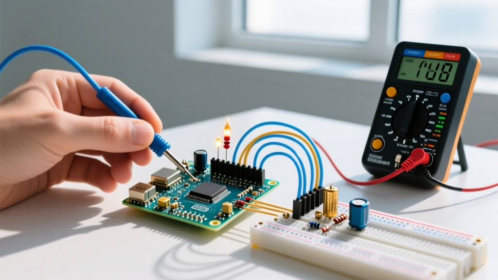
When a circuit fails, measuring voltage and current tells you exactly where the fault lies. Voltage measurements are taken in parallel across a component. If you measure 12V at the power supply but 0V at the load, you have an open circuit (broken wire or blown fuse) between the two points. Current measurements are taken in series (breaking the circuit and inserting the meter). If your 12V motor is supposed to draw 2A but your meter reads 8A, the motor is mechanically binding or the internal windings are shorted, lowering the resistance and causing a massive current spike.
Frequently Asked Questions
What do people most commonly confuse voltage and current with?
Beginners frequently confuse a power source's capacity with the circuit's actual draw. They worry that plugging a 1A device into a 100A car battery will "fry" the device. In reality, the battery simply has the capacity to supply up to 100A; the 1A device will only "pull" the 1A it needs based on its internal resistance. The danger only arises when a low-resistance fault (like a short circuit) occurs, allowing the high-capacity source to push unlimited current through unprotected wires.
Does higher voltage always mean higher current?
No. Current is determined by both voltage and resistance (I = V/R). A static electricity shock from a doorknob can involve 10,000 volts, but the actual current flow is measured in microamps (millionths of an amp) because the resistance of the air gap and your dry skin is astronomically high. Conversely, a 12V car battery can deliver 500 amps to a starter motor because the motor's internal resistance is near zero and the copper cables are incredibly thick. According to Fluke's electrical safety guidelines, it is the current passing through the human body that causes physiological damage, but it requires sufficient voltage to overcome the skin's natural resistance to push that lethal current.
Why do we use high voltage for power transmission?
To minimize $I^2R$ power losses in the wires. Power (Watts) equals Voltage × Current. If a utility needs to deliver 1,000,000 Watts, they can do it at 100V and 10,000A (which would require impossibly thick copper wires to prevent them from melting), or they can step the voltage up to 100,000V and push only 10A. By transmitting at high voltage and low current, they can use relatively thin, lightweight aluminum conductors over hundreds of miles, stepping the voltage back down to safe, high-current levels via transformers at your local neighborhood pole.