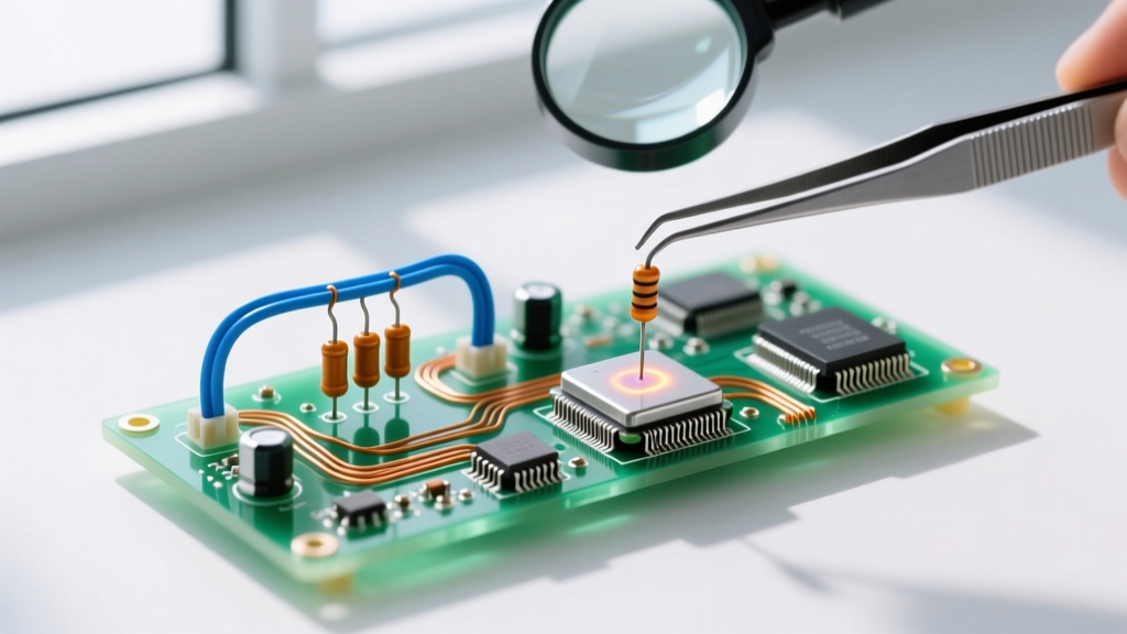
At its most fundamental level, what is a circuit loop? A circuit loop is any closed, continuous conductive path that allows current to flow from a power source, through one or more components, and back to the source without retracing its steps. This concept is the physical manifestation of Kirchhoff’s Voltage Law (KVL), which dictates that the sum of all voltage drops around any closed loop must equal the total applied source voltage. If a path does not close back on itself, it is an open circuit, not a loop.
Understanding loops is not just an academic exercise; it is the basis of every topology decision you make on the bench. Whether you are wiring a string of LEDs or designing a sensor bias network, how you arrange your loops determines your circuit's fault tolerance, power dissipation, and component sizing. Below, we break down loop topology using a practical 12V DC indicator panel, contrasting series and parallel configurations to give you a definitive design path.
Topology Description: Mapping the Nodes
To analyze a loop, we must define its nodes—the specific points where two or more circuit elements connect. Let us map a standard 12V DC multi-LED indicator circuit to see how loops form.
- Node A (Source Positive): The 12V DC supply rail.
- Node B (Anode Junction): The connection point between the positive rail and the LED anodes.
- Node C (Component Junction): The connection point between the LED cathodes and the current-limiting resistors.
- Node D (Source Negative/Ground): The 0V ground rail where the resistors terminate and return to the power supply.
In a series topology, the components share the same loop current. The path goes from Node A → LED 1 → Node C1 → LED 2 → Node C2 → LED 3 → Resistor → Node D. There is only one continuous loop. In a parallel topology, each component (or series-string of components) forms its own independent loop branching off the main nodes. Loop 1 goes Node A → Red LED → Resistor 1 → Node D. Loop 2 goes Node A → Green LED → Resistor 2 → Node D, and so on.
Series vs. Parallel Loops: The Behavior and Failure Matrix
The choice between wiring loads in a single series loop versus multiple parallel loops fundamentally changes how the circuit behaves under normal and fault conditions. The table below contrasts these topologies using our 12V LED indicator example.
| Condition / Event | Single Series Loop (3 LEDs, 1 Resistor) | Independent Parallel Loops (3 Branches) |
|---|---|---|
| Normal Operation | Current is identical through all LEDs. Total voltage drop equals 12V. | Branch currents vary based on individual LED forward voltage (Vf). Total current is the sum of branches. |
| One LED Opens (Fails Open) | Total failure. The single loop is broken. All LEDs go dark immediately. | Partial failure. Only the affected branch goes dark. Other loops continue operating normally. |
| One LED Shorts (Fails Short) | Overcurrent risk. The shorted LED drops 0V. The remaining voltage shifts to the other LEDs and resistor, potentially overdriving them unless the resistor limits the new peak current. | Contained failure. The shorted branch draws maximum current limited only by its dedicated resistor. Other loops are completely unaffected (assuming a stiff voltage source). |
| Voltage Headroom Required | High. Source voltage must exceed the sum of all LED Vf drops. | Low. Source voltage only needs to exceed the highest single LED Vf drop. |
When evaluating what breaks at the extremes, the series loop's fatal flaw is its lack of redundancy. A single mechanical vibration cracking a solder joint on one LED kills the entire panel. The parallel loop isolates faults to individual branches, making it vastly superior for dashboard indicators, status panels, and lighting arrays where partial visibility is better than total blindness.
Design Walkthrough: Sizing Components for a 12V Parallel Loop
Let us design three independent parallel loops for a 12V nominal (13.8V alternator-charged) system. We will use standard 5mm through-hole LEDs. We must calculate the current-limiting resistor for each branch independently because each LED color has a different forward voltage (Vf). We will target a standard 20mA (0.02A) drive current.
Branch 1: Red LED (Lite-On LTL-307EE)
- Forward Voltage (Vf): 2.0V
- Voltage across resistor (Vr): 12V - 2.0V = 10.0V
- Resistance (R = Vr / I): 10.0V / 0.02A = 500Ω
- Concrete Pick: 510Ω (Standard E24 value).
- Power Dissipation (P = I²R): 0.02² × 510 = 0.204W. Pick: 1/2W carbon film resistor (e.g., Vishay PR02 series) to maintain a safe thermal margin above the 1/4W limit.
Branch 2: Green LED (Lite-On LTL-307EE)
- Forward Voltage (Vf): 2.2V
- Voltage across resistor (Vr): 12V - 2.2V = 9.8V
- Resistance: 9.8V / 0.02A = 490Ω
- Concrete Pick: 470Ω (Standard E24 value, yields ~20.8mA, well within the 30mA absolute max).
- Power Dissipation: 0.0208² × 470 = 0.203W. Pick: 1/2W resistor.
Branch 3: Blue LED (Lite-On LTL-307EE)
- Forward Voltage (Vf): 3.2V
- Voltage across resistor (Vr): 12V - 3.2V = 8.8V
- Resistance: 8.8V / 0.02A = 440Ω
- Concrete Pick: 430Ω (Standard E24 value).
- Power Dissipation: 0.02² × 430 = 0.172W. Pick: 1/4W resistor is acceptable here, but standardizing on 1/2W for the whole BOM reduces assembly errors.
Decision Tree: Which Loop Topology Should You Build?
Do not default to 'it depends' when choosing a topology. Use this decision matrix to arrive at a concrete pick for your specific application.
| Design Constraint | If your priority is... | Then choose this topology |
|---|---|---|
| Fault Tolerance | Keeping remaining loads active if one fails open/short. | Independent Parallel Loops |
| Current Matching | Ensuring identical current through every load without individual resistors (e.g., high-power LED strings). | Single Series Loop (with constant current driver) |
| Voltage Headroom | Running many low-voltage loads from a high-voltage source efficiently. | Series-Parallel Hybrid Loops |
| Wiring Simplicity | Minimizing wire runs for long-distance landscape lighting. | Series Loop (specifically constant-current series) |
The Concrete Pick: For standard DC indicator panels, dashboard warning lights, and hobbyist sensor arrays operating from a fixed voltage source (like a 12V battery or 5V USB rail), always choose the independent parallel loop topology with dedicated branch resistors. The slight increase in BOM cost (three 1/2W resistors instead of one) is vastly outweighed by the isolation of failure modes. If one LED dies, your panel still functions, and troubleshooting is as simple as checking one branch at a time.
How to Breadboard and Verify the Parallel Loop
Theory is useless if you cannot verify it on the bench. Here is the exact step-by-step procedure to build and test our 12V parallel LED loops on a standard 830-point solderless breadboard.
- Prepare the Power Rails: Connect your bench power supply set to exactly 12.0V DC to the breadboard. Use red jumper wires for the positive (top) rail and black for the ground (bottom) rail. Safety check: Ensure the supply is in CC (Constant Current) mode with a 100mA limit before turning it on to prevent shorts from melting jumper wires.
- Place the LEDs: Insert the Red, Green, and Blue LEDs into the main terminal strips. Ensure the flat spot (cathode/negative) is on the right side of the breadboard's center trench, and the rounded edge (anode/positive) is on the left.
- Install the Resistors: Insert one leg of the 510Ω, 470Ω, and 430Ω resistors into the same rows as the LED cathodes. Bend the other leg of each resistor down to the negative (ground) power rail.
- Wire the Anodes: Use red jumper wires to connect the anode (left side) of each LED directly to the positive 12V power rail. You now have three distinct, closed circuit loops.
- Energize and Visual Check: Turn on the power supply. All three LEDs should illuminate. If one is dark, check for a straddled connection across the center trench or a reversed LED polarity.
- Verify with a Multimeter (The Crucial Step): Set your DMM to DC millivolts (mV). Place the red probe on the LED cathode side of the 510Ω resistor and the black probe on the ground rail side. You should read approximately 10.2V (10,200mV). Using Ohm's law (I = V/R), 10.2V / 510Ω = 0.020A (20mA). Repeat for the other branches. If your measured voltage yields a current higher than 25mA, your source voltage is sagging or your resistor value is wrong; de-energize and swap the resistor.
By treating each branch as an independent loop and verifying the voltage drop across the known resistance, you confirm that Kirchhoff's Voltage Law holds true in your physical build. For a deeper mathematical breakdown of how KVL applies to complex meshes, review the Electronics Tutorials guide on Kirchhoff's Voltage Law. Mastering loop analysis and topology selection ensures your circuits don't just work on the first day, but survive the inevitable component failures of real-world operation.