
The Core Question: What a Capacitor Actually Does in a Circuit
When beginners first ask what a capacitor is, they are usually handed the "water tank" analogy: a component that stores electrical charge and releases it when needed. While this is fundamentally true from a physics standpoint, it is a dangerous oversimplification for modern PCB prototyping and circuit design. In the real world of RF engineering, audio crossover networks, and switching power supplies, a capacitor is not just an energy bucket; it is a frequency-dependent impedance device, a phase-shifter, and a transient suppressor.
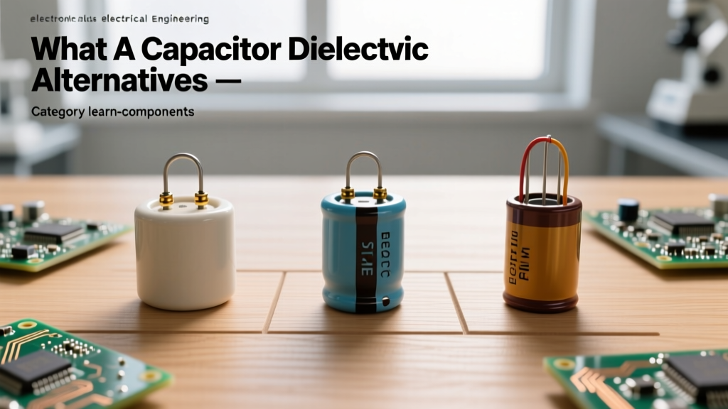
The true behavior of a capacitor is dictated almost entirely by its dielectric material—the insulating layer sandwiched between its conductive plates. To truly understand what a capacitor does in your specific application, you must compare the alternatives. In this guide, we will dissect the three dominant dielectric families used in electronics: Multi-Layer Ceramic (MLCC), Aluminum Electrolytic, and Metallized Film. By comparing their Equivalent Series Resistance (ESR), dielectric absorption, and failure modes, you will learn how to select the exact alternative your prototype demands.
Dielectric Dictates Destiny: Comparing the Big Three
The formula for capacitance is C = (ε × A) / d, where ε is the permittivity of the dielectric, A is the overlapping area of the plates, and d is the distance between them. Manufacturers manipulate these variables differently depending on the dielectric chemistry, leading to wildly different real-world behaviors.
1. Multi-Layer Ceramic Capacitors (MLCC): The High-Frequency Workhorse
Ceramic capacitors, specifically MLCCs, are the undisputed kings of high-frequency decoupling. They are constructed by stacking hundreds of microscopic layers of ceramic dielectric and metal electrodes. According to Murata's technical documentation, the most common dielectrics are Class I (C0G/NP0) and Class II (X7R, X5R).
- C0G/NP0 (Class I): Made from paraelectric materials like titanium dioxide. They offer near-zero temperature coefficients and virtually no DC bias derating. They are the mandatory choice for RF matching networks and precision analog filters.
- X7R/X5R (Class II): Made from ferroelectric barium titanate. They offer massive capacitance in tiny packages (e.g., a 10µF capacitor in an 0805 footprint). However, they suffer from a severe DC bias effect. A 10µF X7R MLCC might drop to just 2µF when its rated 50V is applied.
Prototyping Insight: Class II ceramics are also piezoelectric. If you place an X7R MLCC in a high-ripple current path, it can physically vibrate, emitting an audible "squeal" (microphonic effect). Furthermore, they are highly susceptible to board-flex cracking, which can cause dead shorts.
2. Aluminum Electrolytic: The Bulk Energy Reservoir
When your circuit demands high capacitance at low frequencies—such as smoothing the output of a 60Hz bridge rectifier or buffering a 12V motor driver—MLCCs become economically unviable. This is where aluminum electrolytic capacitors step in. They utilize an etched aluminum foil anode and a liquid or solid electrolyte cathode, achieving massive surface area in a cylindrical can.
Taking the Panasonic EEUFM series as a benchmark, a 1000µF 16V electrolytic capacitor costs pennies and can handle significant ripple current. However, they come with severe trade-offs:
- Polarity Sensitivity: Applying reverse voltage causes the internal dielectric oxide layer to break down, generating gas that can lead to catastrophic venting or explosion.
- High ESR and ESL: The liquid electrolyte and the physical winding of the foils introduce significant Equivalent Series Resistance (ESR) and Inductance (ESL), making them useless for filtering high-frequency digital noise (e.g., a 100MHz microcontroller clock).
- Limited Lifespan: The liquid electrolyte slowly evaporates through the rubber end seal. A standard electrolytic might be rated for 2,000 hours at 105°C. As it dries, ESR skyrockets, eventually causing switching regulators to oscillate and fail.
3. Metallized Film: The Audiophile and High-Voltage Standard
Film capacitors use thin plastic films (Polyester/PET, Polypropylene/PP, or PPS) as the dielectric, often coated with a microscopic layer of zinc or aluminum. They are the gold standard for audio crossovers, AC line filtering (X/Y safety capacitors), and high-voltage snubber circuits.
According to Cornell Dubilier's application guides, the defining feature of metallized film is its self-healing property. If a voltage spike punctures the dielectric, the intense localized heat instantly vaporizes the surrounding metal electrode, isolating the fault and allowing the capacitor to continue functioning with a negligible loss of capacitance.
- Polypropylene (PP): Extremely low dielectric absorption and dissipation factor. Ideal for high-end audio and precision sample-and-hold circuits where "memory effect" (dielectric absorption) would distort the signal.
- Polyester (PET): More compact and cheaper than PP, but suffers from higher temperature drift. Commonly used for general-purpose coupling and bypassing in non-critical audio stages.
Head-to-Head Component Comparison Matrix
To synthesize these alternatives, refer to the comparison table below when evaluating your BOM (Bill of Materials) for your next PCB layout.
| Parameter | MLCC (X7R / C0G) | Aluminum Electrolytic | Metallized Film (PP/PET) |
|---|---|---|---|
| Capacitance Range | 0.5pF to 100µF | 0.1µF to 100,000µF+ | 100pF to 100µF |
| ESR Profile | Ultra-Low (mΩ range) | High to Moderate (Ω to mΩ) | Low to Moderate |
| DC Bias Sensitivity | Severe (X7R) / None (C0G) | Negligible | Negligible |
| High-Frequency Response | Excellent (up to GHz) | Poor (limited by ESL) | Good (limited by lead length) |
| Primary Failure Mode | Flex-cracking (Short circuit) | Electrolyte drying (Open/High ESR) | Corona discharge / Thermal runaway |
| Relative Cost (per µF) | Low (at scale) / High (C0G) | Extremely Low | Moderate to High |
Real-World Failure Modes and Prototyping Pitfalls
Understanding what a capacitor is theoretically means nothing if your prototype fails in the field due to unanticipated physical limitations. Here are three specific failure modes you must design around:
The MLCC Board-Flex Trap: When you depanelize a PCB or screw it into a metal enclosure, the board bends. Because MLCCs are rigid ceramic bricks soldered directly to copper pads, this mechanical stress transfers directly into the ceramic body, causing micro-cracks. These cracks can grow, leading to a dead short that burns up your voltage regulator. Solution: Use "soft-termination" MLCCs (like Kemet's KEMET X7R series) which feature a conductive epoxy layer that absorbs mechanical stress, or keep large MLCCs away from board edges and mounting holes.
The Electrolytic Ripple Current Overheating: Every electrolytic capacitor has a maximum ripple current rating. If you use a cheap, off-brand 100µF capacitor on the output of a 2A buck converter, the internal ESR will cause I²R heating. The capacitor will literally bake itself from the inside out, venting its electrolyte and destroying the PCB traces beneath it. Always calculate the RMS ripple current and select a low-ESR polymer or high-ripple radial alternative.
Film Capacitor dV/dt Limitations: In high-power snubber circuits, film capacitors are subjected to massive, rapid voltage changes (high dV/dt). If the dV/dt exceeds the manufacturer's specification, the internal metallization can delaminate from the plastic film, creating internal arcing and eventual open-circuit failure.
Decision Framework: Which Alternative Wins?
So, what a capacitor ultimately "is" in your circuit depends on the job you assign it. Use this rapid decision framework during your schematic capture phase:
- Is it for RF tuning, precision analog filtering, or crystal oscillator load matching? You must use C0G/NP0 Ceramic. Do not use X7R, or your temperature drift will detune the circuit.
- Is it for decoupling a 3.3V digital IC or an FPGA? Use X7R/X5R MLCCs. Place a 100nF 0402 or 0603 as close to the VCC pin as possible to minimize loop inductance, backed up by a 10µF MLCC for lower-frequency transient response.
- Is it for bulk storage on a 24V DC motor drive or an AC-DC power supply output? Use Aluminum Electrolytic. Ensure the voltage rating is at least 20% above your maximum steady-state voltage, and verify the ripple current rating against your switching frequency.
- Is it for an audio signal path, AC mains filtering, or a high-voltage IGBT snubber? Use Metallized Film. The low dielectric absorption of Polypropylene ensures your audio transients remain crisp, while its self-healing nature guarantees safety across the AC mains.
By moving past the simplistic "water tank" analogy and evaluating the dielectric alternatives, you transform from a hobbyist who merely places components on a board into an engineer who commands the electromagnetic behavior of the circuit. The next time you ask yourself what a capacitor does, remember: it does exactly what its dielectric allows it to do.