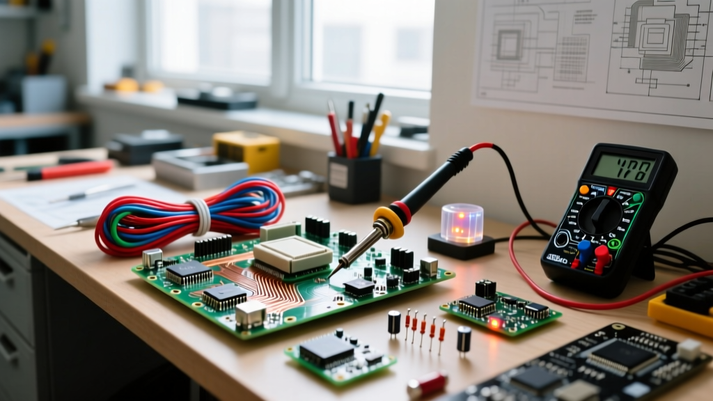
Tristate electronics refers to digital logic circuits that feature three distinct output states—logic HIGH, logic LOW, and a high-impedance (Hi-Z) state that effectively disconnects the output from the circuit. In a real circuit, this third state changes everything by allowing multiple microcontrollers, memory chips, or sensors to share a single physical data bus without short-circuiting each other when inactive. Beginners commonly confuse the Hi-Z state with a logic LOW or a simple broken wire, but Hi-Z is an active, controlled disconnection managed by a dedicated enable pin, leaving the bus floating so another device can safely drive it.
The Three States and Tristate Buffer Specifications
Standard logic gates (like a 74HC04 inverter) output either a solid, low-resistance connection to VCC (HIGH) or GND (LOW). Tristate buffers add a pair of MOSFETs in the output stage that can both be turned off simultaneously. When the Output Enable (OE) pin is deasserted, the output pin enters the Hi-Z state, presenting an impedance typically > 1 MΩ to the rest of the circuit. This effectively removes the chip from the bus electrically.
To select the right component for your bus, you need to look at the specific logic family. Using the wrong family can lead to ground bounce, excessive shoot-through current, or logic level mismatches. Here is a comparison of common tristate buffer ICs used in bench and production designs:
| IC Part Number | Logic Family | VCC Range | Max I_out (Sink/Source) | Propagation Delay (tpd) | Primary Use Case |
|---|---|---|---|---|---|
| SN74LS125 | Low-Power Schottky (Bipolar) | 4.75V - 5.25V | 24 mA / -0.4 mA | ~15 ns | Legacy 5V retro-computing and repair |
| SN74HC125 | High-Speed CMOS | 2.0V - 6.0V | 25 mA / -25 mA | ~18 ns (at 5V) | Standard 5V/3.3V hobby and industrial bus sharing |
| SN74LVC125A | Low-Voltage CMOS | 1.65V - 3.6V | 50 mA / -50 mA | ~5 ns (at 3.3V) | Modern 3.3V/1.8V microcontroller SPI/I2C buses |
| SN74CB3T3245 | FET Bus Switch | 2.3V - 3.6V | N/A (Pass-through) | < 1 ns | High-speed memory address bus isolation |
Worked Numeric Example: Sizing a Pull-Up Resistor for a Hi-Z Bus
When a tristate bus is in the Hi-Z state, it is electrically floating. Electromagnetic interference (EMI) or capacitive coupling from adjacent traces can induce random voltage spikes, causing downstream logic gates to read phantom HIGH/LOW transitions. To prevent this, we use a pull-up (or pull-down) resistor to weakly bias the bus to a known state when no device is driving it.
Let’s calculate the pull-up resistor value for a 5V shared data bus using a Texas Instruments SN74HC125 quad tristate buffer.
- VCC: 5.0V
- Target HIGH voltage (V_IH min): 3.5V (standard threshold for 5V CMOS)
- Hi-Z leakage current (I_OZ): ±1 µA (max at 25°C, per datasheet)
- Number of devices on bus: 4 (total worst-case leakage = 4 µA)
If we want the bus to sit solidly at 4.9V when floating (well above the 3.5V V_IH threshold), we need to drop only 0.1V across the pull-up resistor to supply the leakage current.
Using Ohm’s Law (R = V / I):
R = 0.1V / 4 µA = 25,000 Ω (25 kΩ).
However, we must also verify the LOW state. When a device does drive the bus LOW, it must sink the current from this pull-up resistor without the voltage rising above the maximum LOW threshold (V_IL max = 1.35V for 5V CMOS).
Current through a 25 kΩ resistor at 5V = 5V / 25,000 Ω = 0.2 mA.
The 74HC125 can safely sink up to 25 mA (absolute max) and 6 mA continuously. A 0.2 mA sink requirement is trivial, keeping the LOW voltage near 0.05V. Therefore, a standard 22 kΩ or 27 kΩ pull-up resistor is ideal for this 5V tristate bus, providing noise immunity without overloading the driving IC.
Where You Meet Tristate Logic in Practice
If you are designing embedded systems or repairing digital hardware, you will encounter tristate electronics in several specific architectures:
- SPI MISO Lines: In a multi-slave SPI bus, the Master-In-Slave-Out (MISO) line is shared. As detailed in Analog Devices' SPI interface guides, only the slave with its Chip Select (CS) line asserted will enable its tristate buffer to drive the MISO pin. All other slaves keep their MISO pins in Hi-Z, preventing bus contention.
- Parallel Address/Data Buses: Older SRAM, Flash memory, and retro-computer CPUs (like the Z80 or 6502) use bidirectional data buses. Tristate transceivers (like the 74HC245) route data to and from the CPU, ensuring the memory chip only drives the bus during a READ cycle.
- Multiplexed LED Matrices: High-density LED displays use tristate drivers to isolate rows and columns. By placing unselected rows into Hi-Z, the driver prevents ghosting and reverse-bias leakage through adjacent LEDs.
- JTAG / SWD Debug Headers: Debug probes use tristate buffers to isolate the debug clock and data lines from the target microcontroller when the probe is unpowered, preventing parasitic power draw through the MCU’s internal ESD protection diodes.
Troubleshooting and Common Hi-Z Failures
If two devices attempt to drive a shared bus simultaneously—one outputting HIGH and the other LOW—the PMOS transistor of the HIGH device and the NMOS transistor of the LOW device create a near-short circuit from VCC to GND. This results in a massive current spike (often >100 mA) that causes severe ground bounce, logic errors, and eventual thermal destruction of the silicon. Always verify Output Enable (OE) timing with an oscilloscope to ensure a dead-time (break-before-make) exists between device handoffs.
Frequently Asked Questions
Is an open-drain output the same as a tristate output?
No. An open-drain (or open-collector) output can pull the line LOW or let it float (Hi-Z), but it cannot actively drive the line HIGH. It relies entirely on an external pull-up resistor for the HIGH state (common in I2C). A tristate output can actively drive HIGH, actively drive LOW, or enter Hi-Z.
Why does my microcontroller read random noise when a tristate buffer is disabled?
You are likely missing a pull-up or pull-down resistor. When the buffer enters Hi-Z, the trace becomes a high-impedance antenna. Capacitive coupling from nearby clock traces will induce voltage fluctuations that cross the microcontroller’s logic thresholds. Add a 10 kΩ to 47 kΩ pull-up resistor to the bus.
Can I use a standard logic AND gate instead of a tristate buffer for bus sharing?
No. Standard gates always actively drive their outputs HIGH or LOW. If you tie the outputs of two standard AND gates together, you will cause bus contention and destroy the ICs. You must use dedicated tristate buffers or open-drain drivers for shared lines.
What happens to shoot-through current during the transition to Hi-Z?
When transitioning from HIGH to Hi-Z, the PMOS transistor turns off. If the OE pin timing is poorly designed, there can be a brief nanosecond window where both output transistors are partially on, causing a spike in let-through current (shoot-through). Modern LVC and AUC logic families are designed with optimized edge rates to minimize this transient power dissipation.