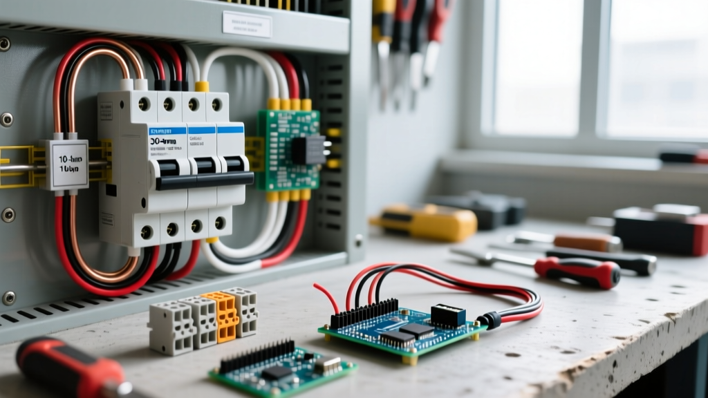
Although the applied voltage during a short circuit (SC) test is reduced, you are still working with equipment rated for mains voltage. Your multimeter, clamp meter, and power analyzer must be rated CAT III 600V minimum (CAT IV 600V preferred if testing at the service entrance). Always de-energize the circuit, apply lockout/tagout (LOTO), and verify dead with a tested meter before installing the shorting jumper on the low-voltage winding.
1. The Short Circuit Test: Purpose and Baseline
The SC test of transformer windings is the definitive bench and jobsite method for determining full-load copper losses (I²R) and calculating the equivalent impedance (Zeq), resistance (Req), and reactance (Xeq). Unlike the open-circuit test, which isolates core losses, the SC test forces rated current through the windings at a fraction of the nominal voltage.
Why does this matter? If you are sizing protective relays, calculating voltage regulation under load, or diagnosing a suspected degraded winding, you need these exact parameters. A transformer's nameplate gives you the impedance percentage (e.g., 5.75%), but aging, loose internal connections, and thermal cycling shift these values over time. The SC test tells you the physical reality of the copper today.
2. Meter Setup and Probe Placement
You cannot perform an accurate SC test with just a standard digital multimeter (DMM). Because the power factor during this test is extremely low (typically 0.1 to 0.2 lagging), a standard DMM measuring Volts × Amps will give you Apparent Power (VA), not True Power (Watts). You must measure true power to find copper losses.
Required Instrumentation
- Voltmeter: Fluke 87V True-RMS DMM.
- Ammeter: Fluke 376 FC True-RMS Clamp Meter.
- Wattmeter: Fluke 435 Series II Power Analyzer or Yokogawa WT3000 (capable of low power factor measurement).
- Voltage Source: Variable AC transformer (Variac) rated for the primary current, or a dedicated transformer test set.
Meter Configuration Block
| Instrument | Dial Position | Lead Jacks / Sensor | Range Setting |
|---|---|---|---|
| Fluke 87V (Volts) | V~ (AC Volts) | Red to V/Ω, Black to COM | Auto (Expecting 10-50V) |
| Fluke 376 (Amps) | A~ (AC Amps) | Jaw clamped around single HV conductor | Auto (Expecting rated HV current) |
| Fluke 435 (Watts) | Power/Energy | Current clamp on HV line, V-leads across HV | Manual range to match Variac output |
Probe Placement
All measurement probes and clamps go on the High-Voltage (HV) primary side. The Low-Voltage (LV) secondary side is strictly used for the shorting connection. Place the Variac output leads on the HV bushings. Place the voltage probes directly on the transformer bushings (inside the current clamp) to avoid measuring the voltage drop across your test leads.
3. Step-by-Step Execution and Expected Readings
The golden rule of the SC test: We short the LV side and energize the HV side. We do this because the rated current on the HV side is lower, making it easier and safer to source the required current with a bench Variac.
- De-energize and Isolate: Disconnect the transformer from all mains and loads. Verify zero energy state.
- Short the LV Winding: Install a heavy-gauge copper jumper across the LV terminals. Crucial: The jumper must have negligible resistance. For a 50A LV rated current, use at least 2 AWG copper wire or a solid copper busbar.
- Connect Meters: Attach the Variac, voltmeter, ammeter, and wattmeter to the HV winding as described above.
- Ramp Voltage Slowly: Start the Variac at 0V. Slowly increase the voltage while watching the ammeter.
- Hit Rated Current: Stop increasing voltage the exact moment the HV ammeter reads the transformer's rated full-load primary current (found on the nameplate).
- Record Data: Immediately log Vsc (Short Circuit Voltage), Isc (Short Circuit Current), and Wsc (Short Circuit Power/Watts).
Expected Reading Table: Good vs. Bad
What does a good reading look like numerically? It is entirely relative to the nameplate, but follows strict percentage boundaries.
| Parameter | Expected 'Good' Reading | 'Bad' Reading (Red Flag) |
|---|---|---|
| Isc (Current) | 100% of Nameplate Rated HV Current | Cannot reach rated current before Variac maxes out |
| Vsc (Voltage) | 5% to 10% of Rated HV Voltage (e.g., 24V - 48V on a 480V primary) | > 15% of rated voltage (indicates severe impedance shift) |
| Wsc (Power) | Within ±5% of Nameplate Load Loss (corrected to ambient temp) | > 110% of Nameplate Load Loss (indicates winding degradation) |
4. Calculating Equivalent Parameters
Once you have your raw data, you need to calculate the equivalent circuit parameters referred to the HV side. These formulas are the bridge between raw bench data and power system modeling.
- Equivalent Impedance (Zeq): Zeq = Vsc / Isc (in Ohms)
- Equivalent Resistance (Req): Req = Wsc / (Isc)² (in Ohms)
- Equivalent Reactance (Xeq): Xeq = √(Zeq² - Req²) (in Ohms)
- Percentage Impedance (%Z): %Z = (Vsc / Vrated) × 100
5. Diagnostic Decision Tree: Interpreting the Results
Data without a decision path is just noise. Use this decision matrix to determine your next physical action based on the SC test of transformer results. This eliminates the 'it depends' guesswork.
| Condition Observed | Probable Root Cause | Concrete Action / Pick |
|---|---|---|
| Wsc is 105-115% of nameplate, %Z is normal | Loose internal bushing connections or tap changer contact resistance. | De-energize, open inspection cover, and retorque all accessible internal busbar lugs to manufacturer spec (usually 40-60 ft-lbs). Retest. |
| Wsc is >115% of nameplate, %Z is high | Winding deformation, inter-turn short degradation, or severe thermal aging of copper. | Replace the transformer. Do not attempt rewinding for units under 500kVA; the labor cost exceeds a new unit (e.g., Hammond Mfg 500kVA padmount). |
| Vsc required to reach Isc is < 3% of rated | Shorted turns in the winding (insulation failure). | Fail the unit immediately. Perform a Sweep Frequency Response Analysis (SFRA) or TTR (Transformer Turns Ratio) test to confirm the exact faulted coil before scrapping. |
| Wsc fluctuates wildly as voltage ramps | Arcing inside the tap changer or loose shorting jumper on the LV side. | Check the LV jumper first. If tight, replace the On-Load Tap Changer (OLTC) contacts or upgrade to a fixed-tap configuration if voltage regulation is handled elsewhere. |
6. Common Mistakes That Skew Your Data
When an SC test yields confusing numbers, the fault is rarely the transformer—it is almost always the test setup. Avoid these three critical errors.
Mistake 1: Using Undersized Shorting Jumpers
If you use a 10 AWG wire to short the LV side of a 100 kVA transformer (which might see 120A on the LV side), that wire will act as a resistor. You will measure the I²R losses of your jumper wire, not the transformer windings. This artificially inflates Wsc, leading you to falsely diagnose high copper losses. Fix: Always use a copper busbar or parallel heavy-gauge cables (e.g., 2/0 AWG) that are physically bolted, not just clipped, to the LV terminals.
Mistake 2: Measuring Power Factor with a Standard DMM
As noted in the setup block, a standard DMM cannot measure true power (Watts) in a highly inductive, low-power-factor circuit. If you multiply your DMM's AC Voltage reading by your Clamp Meter's AC Amp reading, you are calculating Volt-Amps (VA). Because the power factor in an SC test is often around 0.15, your calculated 'Watts' will be nearly 600% higher than reality. Fix: You must use a dedicated wattmeter or power analyzer (like the Fluke 435) that samples instantaneous voltage and current waveforms to calculate true power.
Mistake 3: Ignoring Thermal Drift During Prolonged Testing
Copper resistance increases by roughly 0.4% per degree Celsius. If you leave the Variac on for 20 minutes while troubleshooting a meter issue, the transformer windings will heat up. Your final Wsc reading will be higher than your initial reading simply due to thermal drift. Fix: Keep the test duration under 60 seconds. Ramp up, hit rated current, record the numbers, and immediately ramp the Variac back to zero.
For deeper reading on standardized testing protocols, refer to the IEEE C57.12.90 Standard Test Code for Liquid-Immersed Transformers, which dictates the exact temperature correction formulas and tolerance limits. Additionally, the Electrical Engineering Portal's guide on transformer testing provides excellent visual references for single-phase and three-phase SC test wiring configurations. For instrument selection and low-power-factor measurement theory, review Fluke's official transformer testing application notes.
By strictly adhering to the meter setup, using adequately sized shorting jumpers, and applying the diagnostic decision tree, you will extract actionable, definitive data from every SC test of transformer you perform.