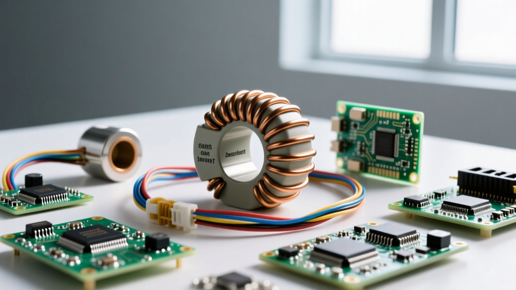

Saturation current ($I_{sat}$) in an inductor is the specific DC bias current at which the component's inductance drops by a defined percentage—typically 20% or 30%—from its zero-bias nominal value. When you push an inductor past this threshold, the magnetic core can no longer store additional flux. The inductor stops acting like a reactive component and begins acting like a low-resistance piece of wire. In switching power supplies, this transition is catastrophic: the current ramp rate ($di/dt$) spikes, and the switching MOSFET usually destroys itself before the controller's overcurrent protection can react.
Unlike RMS current ($I_{rms}$), which is a thermal limit dictated by the wire gauge and ambient temperature, $I_{sat}$ is a strict magnetic limit dictated by the core material and physical geometry. Designing with a 20% to 30% margin above your calculated peak inductor current ($I_{peak}$) is the baseline for reliable power electronics.
Core Material Profiles and Saturation Curves
The way an inductor behaves as it approaches $I_{sat}$ depends entirely on its core material. Ferrite cores hit a magnetic "brick wall," while metal composite cores gracefully roll off. Choosing the wrong profile for your control loop can lead to subharmonic oscillation or immediate short-circuit failures during transient loads.
| Core Material | Saturation Profile | Typical $I_{sat}$ Range | Tempco (Inductance vs Temp) | Typical Use Case |
|---|---|---|---|---|
| MnZn Ferrite | Hard / Sharp (cliffs at $I_{sat}$) | 1A - 15A | -20% to -50% at 100°C | Standard buck/boost converters, isolated flybacks |
| NiZn Ferrite | Hard / Sharp | 0.1A - 5A | -10% to -30% at 100°C | High-frequency RF chokes, EMI filtering (>1MHz) |
| Iron Powder | Soft / Gradual roll-off | 5A - 30A | Stable up to 125°C | PFC chokes, low-cost high-DC-bias filtering |
| Metal Alloy (Composite) | Very Soft / Linear roll-off | 10A - 80A+ | Highly stable (-5% at 125°C) | High-current POL converters, GPU VRMs, automotive |
| Amorphous / Nanocrystalline | Extremely Sharp | 0.5A - 10A | Stable up to 150°C | Saturable reactors, high-end audio crossovers |
If you are designing a Peak Current Mode (PCM) controlled buck converter, a sharp-saturating ferrite core (like the Coilcraft XEL series) can cause the current sense comparator to trip erratically if transient loads push the core into the knee of the saturation curve. For PCM loops, metal composite inductors (like the Würth Elektronik WE-LQOS or Bourns SRP1265A) are vastly superior because their soft saturation maintains a predictable $di/dt$ slope even during overload events.
Decoding SMD Inductor Markings and Datasheet Specs
When you are troubleshooting a board or scavenging parts from a donor PCB, you need to read the physical markings to determine the inductance, which directly correlates to the $I_{sat}$ rating for a given physical footprint.
Reading the Top-Side Codes
Surface mount power inductors use a standardized alphanumeric code to denote nominal inductance. The letter "R" acts as the decimal point for values under 100 µH, while a three-digit system is used for higher values.
- 4R7: 4.7 µH. The "R" replaces the decimal. Common in 5V-to-3.3V buck circuits.
- 100: 10 µH. Read as "10" followed by zero zeros (10 × 10⁰).
- 101: 100 µH. Read as "10" followed by one zero (10 × 10¹).
- 221: 220 µH. Read as "22" followed by one zero (22 × 10¹).
Besides the value, you will often see a manufacturer logo (a small spring for Coilcraft, a red dot or snowflake for Würth) and a date code. The physical volume of the package (e.g., 6x6mm vs 12x12mm) combined with the inductance value gives you a highly accurate estimate of the $I_{sat}$. For example, a shielded 4.7µH inductor in a 6x6x3mm package will almost universally have an $I_{sat}$ between 3.5A and 5.0A, regardless of the manufacturer.
The $I_{sat}$ vs. $I_{rms}$ Datasheet Trap
Datasheets list both $I_{sat}$ and $I_{rms}$ (or $I_{dc}$). $I_{sat}$ is your magnetic ceiling; $I_{rms}$ is your thermal ceiling. Your design must satisfy both. If your peak transient current is 4A, and your continuous average current is 2A, you need an inductor with $I_{sat} > 4.8A$ (assuming a 20% margin) and $I_{rms} > 2.5A$ (assuming a 25% thermal margin). Always check the temperature rise graphs in the datasheet; an inductor might have a 5A $I_{rms}$ rating, but that might be predicated on a 40°C temperature rise, which could cook adjacent components on a densely packed PCB.
Failure Modes: What Happens When You Exceed $I_{sat}$
To understand the failure mechanism, look at the fundamental inductor equation: $V = L \cdot (di/dt)$. Rearranged for the current ramp rate, we get $di/dt = V / L$.
In a 12V-to-1V buck converter, when the high-side MOSFET turns on, the voltage across the inductor is roughly 11V. If your nominal inductance is 2.2µH, the current ramps at a controlled 5 A/µs. However, if a massive load transient pushes the core into saturation and the inductance drops by 80% to 0.44µH, the ramp rate violently spikes to 25 A/µs.
Visual Symptoms on the PCB
When this happens, the current sense resistor or the controller's internal current limit cannot react fast enough to shut off the gate drive. The inductor current runs away until it exceeds the absolute maximum drain current ($I_{D}$) of the MOSFET.
- The MOSFET: You will see a blistered, cracked, or exploded epoxy package on the switching FET. In severe cases, the silicon die physically pops off the leadframe.
- The PCB: Look for charred FR4 material directly under or immediately adjacent to the MOSFET, not the inductor. The inductor's copper windings usually survive the brief microsecond spike before the FET fails open or short.
- The Inductor: It will often look perfectly pristine. This is the hallmark of a saturation failure. If the inductor itself is scorched or the solder is melted, you likely exceeded $I_{rms}$ (thermal failure), not $I_{sat}$ (magnetic failure).
Safe Substitution: Swapping Inductors on the Bench
Supply chain shortages frequently force engineers to substitute inductors. Swapping a 4.7µH inductor for another 4.7µH inductor is not safe unless you verify three specific parameters. Use the TI Power Stage Designer Tool or manual calculations to verify your margins before soldering the replacement.
Rule 1: Match or Exceed the Peak Current Margin
Calculate your actual peak inductor current ($I_{peak}$), which is the average load current plus half the ripple current ($\Delta I_L$). Your substitute part must have an $I_{sat}$ rating that is at least 120% to 130% of this $I_{peak}$ value. Never substitute based solely on the continuous load current.
Rule 2: Beware the DCR Slope-Compensation Trap
If you are using Peak Current Mode control, the controller relies on the voltage drop across the inductor's DC Resistance (DCR) or a sense resistor to stabilize the control loop. If your original BOM part had a DCR of 45mΩ, and you substitute a "better" low-DCR composite inductor with 8mΩ, you may accidentally remove the natural slope compensation your loop relied on. This results in subharmonic oscillation at 50% duty cycle, manifesting as audible whining and massive output voltage ripple. If you drop the DCR significantly, you must add an external ramp to the current sense pin.
Rule 3: Shielded vs. Unshielded
You can safely substitute an unshielded inductor (like a drum core) with a shielded one (like a molded composite or shielded ferrite). You cannot safely substitute a shielded inductor with an unshielded one without re-running EMI testing. The fringing flux from an unshielded drum core will couple into nearby high-impedance traces, potentially causing erratic behavior in sensitive analog feedback loops or failing radiated emissions testing.
Quick Reference: Type Selection Matrix
Use this matrix to select the correct inductor topology based on your specific circuit requirements, balancing saturation current, EMI, and cost.
| Application Scenario | Recommended Core Type | Why It Wins Here | Trade-offs to Accept |
|---|---|---|---|
| High-Current GPU/CPU VRM (20A+) | Metal Composite (Molded) | Soft saturation prevents runaway $di/dt$; excellent thermal coupling to PCB. | Higher core losses at high frequencies; expensive. |
| Standard 2A-5A Point-of-Load Buck | Shielded Ferrite | Low core loss at 500kHz-2MHz; cheap; predictable hard saturation. | Must carefully calculate transient peaks to avoid the saturation cliff. |
| Boost Converter (LED Driver) | Unshielded Ferrite Drum | Lowest cost; high inductance values in small footprints; high $I_{sat}$ for size. | Massive fringing flux; cannot be placed near Hall sensors or feedback traces. |
| Power Factor Correction (PFC) Choke | Iron Powder / Sendust | Inherent soft saturation handles the 120Hz AC envelope without clipping. | High core losses; runs hot; requires thermal management. |
| RF Matching / High-Freq Filter (>5MHz) | NiZn Ferrite / Ceramic | High resistivity prevents eddy current losses; stable Q factor. | Very low $I_{sat}$ (often <100mA); useless for power conversion. |
By treating $I_{sat}$ as a hard magnetic boundary rather than a flexible guideline, and by understanding how core materials behave when pushed past that boundary, you can design power stages that survive real-world load transients and safely navigate component substitutions without returning to a bench covered in blown silicon.


