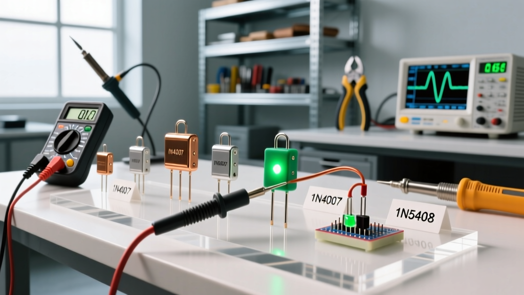

When you look at a diode on a schematic, it is just a one-way valve for current. But on the workbench, diode characteristics like forward voltage drop ($V_F$), peak inverse voltage (PIV), and reverse recovery time ($t_{rr}$) dictate whether your circuit will run efficiently, overheat, or blow up your switching transistors. Understanding these parameters is the difference between a power supply that hums quietly and one that radiates EMI and melts its traces.
In this guide, we bypass the abstract semiconductor physics and focus strictly on applied circuit behavior: how to read a datasheet, select the right default part number, bias it correctly, and test it when things go wrong.
The Core Diode Characteristics and Safe Defaults
Before selecting a part, you need to understand the physical pinout and the schematic symbol. The schematic symbol consists of a triangle (pointing in the direction of conventional current flow) hitting a vertical bar. The physical component (typically in a DO-41 glass or plastic package) has a silver or black ring on one end. That ring marks the Cathode (K). The unmarked lead is the Anode (A). Current flows from Anode to Cathode.
A diode operates in three distinct regions depending on the applied voltage. Here is how those regions manifest in a real circuit:
| Region | Bias Condition | Typical Voltage / Current Behavior | Practical Circuit Impact |
|---|---|---|---|
| Forward Bias | Anode more positive than Cathode ($V_A > V_K$) | Voltage clamps at $V_F$ (0.2V to 1.1V). Current rises exponentially. | Generates heat ($P = V_F \times I_F$). Requires thermal management at high currents. |
| Reverse Bias | Cathode more positive than Anode ($V_K > V_A$) | Blocks current. Microamp-level leakage ($I_R$) flows. | Acts as an open switch. Leakage increases with temperature. |
| Breakdown | Reverse voltage exceeds PIV rating | Avalanche effect. Massive, uncontrolled reverse current. | Destructive for standard rectifiers. Results in a shorted or exploded component. |
The "Grab-Bag" Safe Defaults
If you are prototyping and need a diode, do not guess. Keep these four part numbers stocked on your bench. They cover 95% of hobbyist and light-industrial applications. Note the critical differences in reverse recovery time ($t_{rr}$), which dictates whether a diode can handle high-frequency switching (like in a buck converter) or just 50/60Hz mains rectification.
| Part Number | Type | PIV (Max Reverse Voltage) | Max $I_F$ (Continuous) | Typical $V_F$ @ 1A | Reverse Recovery ($t_{rr}$) |
|---|---|---|---|---|---|
| 1N4148 | Small Signal | 100V | 300mA | 1.0V @ 10mA | 4 ns (Fast) |
| 1N4007 | Standard Rectifier | 1000V | 1.0A | 1.1V | 30 µs (Very Slow) |
| 1N5819 | Schottky | 40V | 1.0A | 0.6V | N/A (Majority Carrier) |
| UF4007 | Ultrafast Rectifier | 1000V | 1.0A | 1.7V | 75 ns (Fast) |
Biasing and Selecting the Right Diode for the Job
Diodes are rarely placed directly across a voltage source without a current-limiting element, because their forward voltage drop ($V_F$) is relatively fixed, but their dynamic resistance drops to near zero once conducting. If you connect a 5V source directly across a 1N4148, the diode will try to clamp the voltage to 1.0V, drawing infinite current until it vaporizes.
Calculating the Bias Resistor
To bias a diode safely, you must calculate a series resistor based on your desired forward current ($I_F$). The formula is derived from Kirchhoff's Voltage Law:
R = (V_source - V_F) / I_F
Worked Example: You want to use a 1N4148 as a clamping diode in a 5V logic circuit, and the datasheet recommends a test current of 20mA for optimal switching speed.
$R = (5V - 1.0V) / 0.020A = 200\Omega$.
You would select the next standard E12 resistor value up, which is 220Ω, to provide a slight safety margin.
Selection Framework: Which Diode Wins?
- Choose Schottky (1N581x) when: You are building a low-voltage DC-DC buck/boost converter, reverse-polarity protection for battery circuits, or solar panel bypass paths. The low $V_F$ (0.2V - 0.6V) minimizes power loss and heat.
- Choose Standard Rectifier (1N400x) when: You are rectifying 50/60Hz AC mains via a transformer, or building a slow-switching relay flyback snubber. They are cheap, robust, and handle high surge currents ($I_{FSM}$ of 30A for one cycle).
- Choose Ultrafast (UF400x) when: You are designing the secondary-side rectifier for a high-frequency flyback or forward switching power supply (20kHz to 100kHz+).
- Choose Signal (1N4148) when: You are routing logic signals, building analog audio distortion pedals, or creating high-speed digital clamping networks.
Application Circuit: 12V Relay Driver with Flyback Protection
Let's look at a complete, practical application that uses two different diodes based on their specific characteristics. When driving an inductive load like a relay coil with a transistor, the collapsing magnetic field generates a massive reverse voltage spike (inductive kickback) that will instantly punch through the collector-emitter junction of your switching transistor.
We will use a 1N4007 for reverse polarity protection on the main 12V rail, and a 1N4148 as the flyback diode across the relay coil.
Component List and Values
- V1: 12V DC Power Supply
- D1 (Polarity Protection): 1N4007 (Anode to V1+, Cathode to Load +12V rail)
- Q1 (Switch): 2N2222 NPN Transistor
- R1 (Base Resistor): 1kΩ (Limits base current from microcontroller GPIO)
- K1 (Load): 12V DC Relay Coil (Approx. 500Ω, drawing ~24mA)
- D2 (Flyback): 1N4148 (Cathode to +12V rail, Anode to Q1 Collector)
How the Characteristics Apply Here
D1 (1N4007): If the user wires the 12V battery backward, D1 becomes reverse-biased. Its 1000V PIV easily blocks the 12V reverse potential, and its microamp leakage ensures the circuit simply stays off without draining the battery. Its 1.1V forward drop will reduce the relay rail to 10.9V, which is perfectly within the pull-in tolerance of a standard 12V relay.
D2 (1N4148): When Q1 turns off, the relay coil's collapsing field drives the collector node negative relative to ground, effectively pushing the cathode of D2 below its anode. D2 instantly forward-biases, creating a short loop for the inductive current to dissipate safely as heat in the coil's internal resistance. We use the 1N4148 here instead of the 1N4007 because its 4ns reverse recovery time ensures it clamps the spike before the voltage can ring and damage nearby sensitive logic ICs.
Failure Modes and Multimeter Testing
Diodes are rugged, but they do fail. According to All About Circuits, semiconductor failures usually stem from thermal or electrical overstress. Understanding how they fail helps you diagnose dead boards faster.
How Diodes Fail
- Short Circuit (Thermal Meltdown): The most common failure. If continuous forward current exceeds the 1A rating of a 1N4007 without adequate heatsinking, the silicon junction melts and fuses into a dead short. You will measure near 0Ω in both directions.
- Open Circuit (The Fuse Effect): If a massive, instantaneous surge current (exceeding the $I^2t$ rating) hits the diode, the tiny internal bond wire vaporizes. The diode acts as an open switch in both directions.
- Leakage Degradation: Prolonged operation near the maximum junction temperature ($T_J$, usually 150°C) causes the reverse leakage current ($I_R$) to permanently increase. The diode still blocks, but it gets hot and wastes power.
Testing with a Digital Multimeter (DMM)
Never use the resistance (Ohms) setting to test a diode; the test voltage is too low to forward-bias the junction. Always use the dedicated Diode Test mode (usually marked with the diode symbol), which outputs enough voltage to turn the junction on and measures the actual $V_F$ drop. As noted by Fluke's testing guidelines, this is the only reliable way to check junction health.
Step-by-Step Bench Test:
- Isolate the component: If possible, remove the diode from the circuit. In-circuit testing often yields false "short" readings because parallel resistors or transformer windings bypass the meter's test current.
- Set the DMM: Turn the dial to the diode test symbol.
- Forward Bias Test: Place the Red probe on the Anode (unmarked end) and the Black probe on the Cathode (silver band).
- Standard Silicon (1N4007/1N4148): Should read between 0.500V and 0.800V.
- Schottky (1N5819): Should read between 0.150V and 0.350V.
- Reverse Bias Test: Swap the probes (Black to Anode, Red to Cathode). The meter should display "OL" (Over Limit) or "1" on the left side of the screen, indicating infinite resistance.
- Verdict: If both directions read "OL", the diode is open. If both directions read a low voltage or near 0Ω, the diode is shorted. If the reverse direction reads a specific voltage lower than "OL" (e.g., 0.4V), the junction is leaky and degraded.
By internalizing these practical diode characteristics—matching the recovery time to your switching frequency, respecting the thermal limits of the DO-41 package, and testing with the right DMM mode—you will eliminate the most common, frustrating points of failure in your power and logic circuits. For deeper mathematical modeling of semiconductor junctions, refer to the comprehensive guides at Electronics Tutorials.


