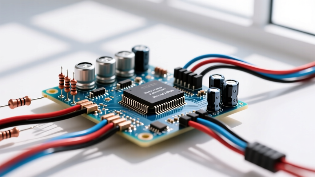
A power on resistor—technically known as an inrush current limiter (ICL)—is a component placed in series with an AC or DC supply line to restrict the initial surge of current when charging bulk filter capacitors. If you are building or repairing a power supply with more than a few thousand microfarads of capacitance, you need one. The direct answer for selection: Use an NTC (Negative Temperature Coefficient) thermistor for continuous loads under 300W where the unit stays powered on. Use a fixed wirewound power resistor bypassed by a relay or triac for high-power (>500W) supplies, industrial motor drives, or equipment that is rapidly cycled on and off.
The Anatomy of an Inrush Spike (Why You Need a Power On Resistor)
When you flip the power switch on a linear supply or a high-wattage audio amplifier, the uncharged bulk filter capacitors initially present a near-zero impedance path to the source. In circuit theory, the current through a capacitor is defined by the equation I = C(dv/dt). If the voltage step (dv) happens almost instantaneously (dt approaches zero), the theoretical current approaches infinity.
In the real world, the current is limited by the equivalent series resistance (ESR) of the capacitors, the winding resistance of the transformer, and the impedance of your wall wiring. However, even with these parasitic resistances, plugging a 120VAC line into a supply with 20,000µF of bulk capacitance can easily generate an initial current spike of 50A to 150A for the first few milliseconds. Without a power on resistor, this massive surge will vaporize slow-blow fuses, pit the contacts of your power switch, and eventually cause catastrophic thermal failure in your bridge rectifier diodes. As detailed in Analog Devices' technical guides on inrush calculation, managing this dv/dt transient is mandatory for reliable power system design.
NTC Thermistors vs. Fixed Wirewound: Component Selection Matrix
Choosing the right power on resistor depends entirely on your steady-state current, duty cycle, and thermal environment. Below is the selection matrix to determine which type wins for your specific job.
| Criteria | NTC Thermistor (e.g., Ametherm SL32) | Fixed Wirewound + Bypass (e.g., Ohmite 12FR) |
|---|---|---|
| Construction | Sintered metal oxide disc with epoxy coating and radial tinned copper leads. | Ceramic or aluminum-housed resistive wire wound around a fiberglass core. |
| Tolerance (R25) | Typically ±10% to ±20%. | Typically ±1% to ±5%. |
| Tempco / Behavior | Negative. High cold resistance (e.g., 10Ω) drops to <1Ω as it self-heats from load current. | Fixed. Resistance remains constant regardless of temperature (minor drift, ±300 ppm/°C). |
| Bypass Required? | No. Relies on self-heating. Must stay in-circuit. | Yes. Requires a timer relay, triac, or MOSFET to short it out after 100-500ms. |
| Power Dissipation | High at steady state (wastes 1W-5W as heat continuously). | Zero at steady state (bypassed, no continuous heat generation). |
| Typical Use Case | Consumer electronics, PC power supplies, audio amps <300W, LED drivers. | Server PSUs, industrial VFDs, high-power linear supplies, rapidly cycled equipment. |
Selection Rule: If your device is turned on, left on for hours, and draws less than 10A, use an NTC. If your device draws 20A+ or is switched on and off multiple times a minute (where an NTC wouldn't have time to cool down and regain its high cold resistance), you must use a wirewound resistor with an active bypass circuit.
Decoding the Markings: Reading the Physical Part
When you pull a salvaged power on resistor from a blown PCB, the markings can look like a cryptic code. Here is how to read them so you can source a replacement.
Radial Epoxy NTC Thermistors
Most generic Asian-manufactured NTCs (and many TDK EPCOS variants) use a three-part alphanumeric code stamped on the epoxy, such as 10D-11 or 5D-20.
- First Number (10 or 5): The zero-power resistance at 25°C (R25) in ohms. A '10' means 10Ω cold.
- Letter (D): Denotes the physical shape. 'D' stands for Disc. You may occasionally see 'S' for chip/surface mount.
- Second Number (11 or 20): This is where manufacturers diverge. In many standard lines, this indicates the maximum steady-state current in Amps (e.g., 11A). However, in other common lines (like Murata or generic Chinese clones), this number indicates the diameter of the disc in millimeters (e.g., 20mm). A 20mm disc typically handles 8A-10A. Always cross-reference the diameter with a datasheet to confirm the current rating.
Ceramic/Aluminum Wirewound Resistors
Fixed power resistors follow standard IEC resistor color codes or direct alphanumeric printing. A marking like 5W 10R J means:
- 5W: Maximum continuous power dissipation rating.
- 10R: Resistance value. The 'R' acts as a decimal point or unit marker. 10R = 10Ω; 4R7 = 4.7Ω; R10 = 0.1Ω.
- J: Tolerance code. J = ±5%, K = ±10%, F = ±1%.
Bench War Story: The 500W Amplifier Power-On Failure
To understand why spec-sheet numbers matter, let us walk through a real-world bench failure involving a DIY 500W Class-AB audio amplifier.
The Setup: The amplifier ran on dual 50VDC rails with 20,000µF of total bulk capacitance. The builder installed a generic 10D-11 NTC thermistor (10Ω cold, 11mm diameter, rated for roughly 5A maximum steady-state current) in series with the primary side of the toroidal transformer.
The Numbers: At idle, the amp drew 1.5A. During loud bass transients, the primary current spiked to 8A. The theoretical inrush without a limiter was calculated at 145A. With the 10Ω cold NTC, the inrush was safely clamped to roughly 17A (170V peak / 10Ω).
The Outcome: The amplifier worked perfectly on the bench for about 15 minutes. Then, during a high-volume test track, there was a loud pop, the main 10A slow-blow fuse blew, and the chassis filled with acrid smoke. The bridge rectifier had shorted.
What Went Wrong: The builder confused the inrush rating with the steady-state rating. The NTC was rated for 5A continuous. The amplifier's musical transients were pulling 8A. Because the current exceeded the NTC's steady-state rating, the thermistor overheated. Its epoxy coating cracked, and the internal element degraded. When the builder replaced the fuse and powered the unit back on immediately, the NTC was still hot. Its resistance was near 0Ω. It failed to limit the inrush, sending the full 145A spike straight into the bridge rectifier, destroying it.
Visual Symptoms of Power On Resistor Failure
- NTC Thermal Runaway: The black epoxy coating shows spiderweb cracking or bubbling. It smells strongly of burning phenolic resin. A multimeter will read near 0Ω even when the part is stone cold.
- Wirewound Open Circuit: The green or gray ceramic casing looks perfectly pristine, but the multimeter reads 'OL' (infinite resistance). This is caused by the internal nichrome wire snapping from thermal shock during a massive inrush event.
- Bypass Relay Welding (Wirewound systems): The resistor tests fine, but the fuse blows on cold boot. The bypass relay contacts have micro-welded together in the closed position, meaning the resistor is permanently bypassed and provides zero inrush protection on startup.
Safe Substitution Rules When the Exact Part is Unavailable
When you are troubleshooting a dead PCB and do not have the exact OEM power on resistor in your bin, you can substitute safely if you follow strict electrical rules. As noted in All About Circuits' component guides, improper substitution is a leading cause of secondary component damage.
- Never Substitute a Lower Steady-State Current Rating: You can safely use a 10Ω NTC rated for 8A in place of a 10Ω NTC rated for 5A. You cannot go the other direction. The physical mass of the larger part handles the continuous heat better.
- Increasing Cold Resistance is Safe (With a Caveat): Substituting a 15Ω NTC for a 10Ω NTC will lower the inrush spike further, which is great for the rectifier. However, you must calculate the steady-state voltage drop. At 5A, a 15Ω NTC might drop 3V to 5V once hot (dropping to ~1Ω). If your downstream switching supply has a tight undervoltage lockout (UVLO), this drop might cause it to chatter or fail to start.
- NEVER Put NTC Thermistors in Parallel: This is a critical bench mistake. If you parallel two 20Ω NTCs to get 10Ω, they will not share current equally. Due to manufacturing tolerances, one will heat up slightly faster. Because it is an NTC, its resistance will drop, causing it to hog even more current, which heats it further. This positive feedback loop guarantees thermal runaway and destruction of the weaker part. Always use a single, properly sized NTC.
- Wirewound Substitution via Series/Parallel: Unlike NTCs, fixed wirewound resistors have a positive temperature coefficient and do not suffer from thermal runaway in parallel. You can safely parallel two 20Ω 10W wirewound resistors to achieve a 10Ω 20W equivalent. Ensure the combined wattage rating is at least double the expected steady-state $I^2R$ dissipation before the bypass relay clicks in.
By matching the steady-state thermal capacity to your actual load profile—and never assuming an 11mm disc can handle 15A of audio transient current—you ensure your power supply survives the violent physics of the power-on event.