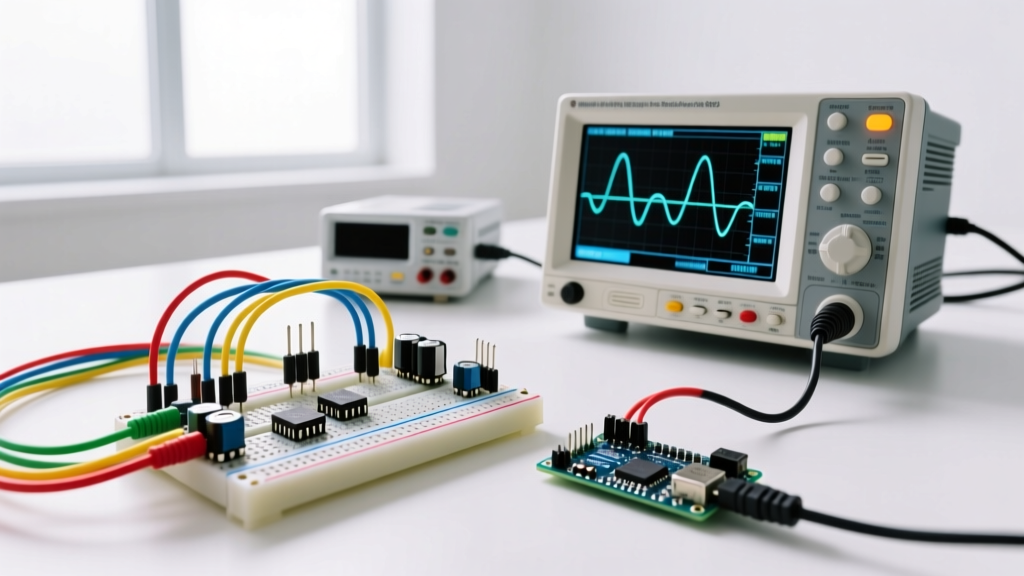
The defining rule of any parallel topology is straightforward: the parallel circuit voltage is identical across every branch connected between the same two nodes. If your positive rail is at 12.0V and your ground rail is at 0.0V, every single component bridging those two rails experiences exactly 12.0V, regardless of its individual resistance or current draw. Current divides; voltage remains constant.
This principle is the backbone of modern power distribution, from household AC wiring to 12V DC automotive and solar systems. Below, we will break down the node topology, calculate real component values for a mixed 12V load, analyze catastrophic failure modes, and walk through a bench-test procedure.
The Core Rule: Node Topology and Voltage Constancy
To understand why parallel circuit voltage remains constant, you must look at the circuit through the lens of nodes rather than individual components. A node is simply a continuous conductive path where no components are interrupting the flow.
In a standard parallel layout, we define two primary nodes:
- Node A (Source Rail): The continuous top wire connected directly to the positive terminal of the power supply.
- Node B (Return Rail): The continuous bottom wire connected directly to the negative/ground terminal.
Because ideal wires have zero resistance, there is no voltage drop along Node A or Node B. Therefore, the potential difference between Node A and Node B is fixed by the power supply. According to Kirchhoff’s Voltage Law (KVL), any closed loop in a circuit must sum to zero volts. If you trace a loop from the supply, through Node A, down through Branch 1, and back through Node B, the voltage dropped across Branch 1 must equal the source voltage. This holds true for Branch 2, Branch 3, and so on. As detailed in foundational DC theory from All About Circuits, adding more branches does not change the voltage across existing branches; it only increases the total current drawn from the source.
Branch Analysis: A Real 12V Mixed-Load Design
Theory is clean, but jobsite and workbench designs require managing mixed loads. Let us design a 12V DC parallel circuit with three distinct branches: an electromechanical relay, a status indicator LED, and a cooling fan.
The Components:
- Branch 1 (Switching): Omron G5V-2 12VDC DPDT relay. Datasheet coil resistance is 288Ω.
- Branch 2 (Indication): Kingbright WP7113SRD Super Bright Red LED. Forward voltage ($V_f$) is 1.8V, target current ($I_f$) is 20mA. Requires a current-limiting resistor.
- Branch 3 (Cooling): Noctua NF-A4x10 12V PWM fan. Nominal draw is 0.1A (1.2W), presenting an equivalent running resistance of roughly 120Ω.
For Branch 2, we must calculate the current-limiting resistor. The parallel circuit voltage across the entire branch is 12V, but the LED only drops 1.8V. The resistor must drop the remaining 10.2V at 20mA. Using Ohm's Law: $R = 10.2V / 0.02A = 510\Omega$. The power dissipated by this resistor is $I^2R = (0.02)^2 \times 510 = 0.204W$. A standard 1/4W (0.25W) resistor will work, but it will run hot to the touch. For reliability, a 1/2W resistor is the better engineering choice.
| Branch | Component(s) | Nominal Resistance | Voltage Drop | Current Draw | Power Dissipation |
|---|---|---|---|---|---|
| 1 | Omron G5V-2 Relay Coil | 288 Ω | 12.0 V | 41.7 mA | 0.50 W |
| 2 | 510Ω Resistor + Red LED | 600 Ω (total) | 12.0 V (10.2V + 1.8V) | 20.0 mA | 0.24 W |
| 3 | Noctua 40mm 12V Fan | 120 Ω (equiv.) | 12.0 V | 100.0 mA | 1.20 W |
| Total Circuit (Node A to B) | ~74 Ω (equivalent) | 12.0 V | 161.7 mA | 1.94 W | |
Notice that the equivalent resistance of the entire parallel network (74Ω) is lower than the lowest individual branch resistance (120Ω). This is a hallmark of parallel topologies: every new branch provides an additional path for current, reducing the overall resistance seen by the power supply.
Failure Modes: What Breaks at the Extremes?
Understanding parallel circuit voltage requires knowing how the topology reacts when things go wrong. The two extremes are an open circuit (a broken wire or blown component) and a short circuit (Node A and Node B touching directly).
For deeper analysis on parallel DC network fault conditions, Electronics Tutorials provides excellent baseline models for how current redistributes during fault states.
| Condition | Node A-B Voltage | Total Current | Branch 1 (Relay) | Branch 2 (LED) | Branch 3 (Fan) |
|---|---|---|---|---|---|
| Normal Operation | 12.0 V | 161.7 mA | Energized | Illuminated | Spinning |
| Branch 2 Open (LED fails) | 12.0 V | 141.7 mA | Energized | Dead (0 mA) | Spinning |
| Branch 3 Short (Fan wires touch) | Collapses to ~0.5 V | Spikes to Supply Limit | Drops out | Extinguished | Dead / Melted |
Why Parallel Over Series for Voltage Distribution?
If you were to wire the Omron relay, the LED, and the Noctua fan in series, the 12V source would divide among them based on their resistances. The fan (120Ω) would drop roughly 7.2V, the relay (288Ω) would drop 17.2V (which exceeds our 12V source, meaning the math shifts as the fan stalls), and the LED would likely be destroyed by overvoltage or fail to illuminate due to insufficient current.
Series circuits are current-controlled; parallel circuits are voltage-controlled. You choose a parallel topology when:
- Components require different operating voltages or currents (e.g., a 12V fan and a 1.8V LED).
- Independent operation is required. If the fan dies in a parallel circuit, the relay still holds its contacts. In a series circuit, one open component kills the entire string.
- You need to maintain a stable bus voltage. Microcontrollers, sensors, and logic ICs rely on rock-solid VCC rails. Parallel distribution ensures that a sudden current spike from a motor (Branch 3) does not proportionally starve a logic chip of voltage, provided the power supply can handle the transient load.
Step-by-Step Breadboard Verification
Do not trust the display on your bench power supply. Always verify parallel circuit voltage at the physical nodes using a calibrated digital multimeter (DMM). Here is the exact procedure for testing the 12V mixed-load circuit described above.
Required Tools:
- Bench Power Supply (e.g., Rigol DP832 or Korad KA3005P) with Over Current Protection (OCP).
- True-RMS Multimeter (e.g., Fluke 117 or Brymen BM235).
- Solderless breadboard and 22 AWG solid-core jumper wires.
- Configure the Supply Limits: Before connecting the circuit, set the power supply to 12.0V. Set the current limit (OCP) to 0.30A (300mA). This provides a 50% buffer above our calculated 161.7mA draw, but will instantly trip and protect the board if a short circuit occurs.
- Wire the Nodes: Run a red jumper from the supply positive to the top breadboard rail (Node A). Run a black jumper from the supply negative to the bottom rail (Node B). Use heavy-gauge wire for the main rails if pulling over 1A, though 22 AWG is fine for this 160mA test.
- Insert Components: Place the relay across the rails. Place the 510Ω resistor in series with the LED, ensuring the LED cathode (short leg) faces Node B. Plug the fan leads into the rails.
- Measure Source Voltage: With the circuit de-energized, connect your DMM probes to the power supply output terminals. Turn on the supply. Verify it reads 12.00V DC.
- Measure Node Voltage Under Load: Move the DMM probes directly to the breadboard rails (Node A and Node B). The reading should remain between 11.95V and 12.00V. If it drops below 11.8V, your jumper wires are too thin or the breadboard contacts are oxidized, introducing unwanted series resistance.
- Verify Branch Currents (Optional): To confirm individual branch behavior, break the connection to Node A for Branch 2, and insert the DMM in series (set to mA mode). You should read exactly 20mA (±1mA depending on resistor tolerance).
By treating the circuit as a set of shared voltage nodes rather than a single continuous loop, you can design, troubleshoot, and scale parallel systems with confidence. The parallel circuit voltage remains your anchor point; as long as Node A and Node B are stable, your independent branches will operate exactly as their individual datasheets dictate.