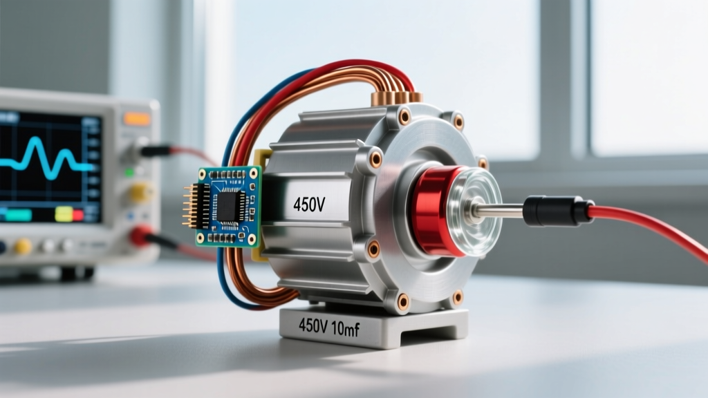
At its core, a 3 phase electric motor is an electromechanical device that converts three alternating currents—offset by 120 electrical degrees—into rotational mechanical energy. Unlike single-phase motors that require capacitors or centrifugal switches to create a starting torque, a three-phase supply naturally generates a Rotating Magnetic Field (RMF) in the stator. This RMF drags the rotor along, delivering smooth, high-torque rotation from zero RPM without the need for commutators or brushes in standard induction designs.
If you are specifying drives for industrial machinery, HVAC systems, or heavy workshop equipment, understanding what a 3 phase electric motor is goes far beyond the basic physics. You need to know how to terminate the windings, match the motor design to the load inertia, and diagnose the subtle electrical faults that destroy bearings and melt insulation. This guide breaks down the practical engineering, sizing math, and failure modes you will encounter on the jobsite.
The Core Physics and Terminal Wiring
The defining advantage of three-phase power is constant power transfer. In a single-phase system, power drops to zero twice per cycle. In a three-phase system, as one phase crosses zero, the other two are still delivering power. This results in a drastically smoother torque output and allows the motor to be physically smaller and lighter for the same horsepower rating.
Terminal Identification and Peckerhead Wiring
When you open the terminal box (peckerhead) of a standard IEC or NEMA 3-phase induction motor, you will typically find six or nine leads. Correctly identifying and jumpering these leads is critical; wiring a 230V Delta motor in a Wye configuration will result in roughly one-third of the rated torque and immediate stalling under load.
| Winding | IEC Designation | NEMA Designation | Function |
|---|---|---|---|
| Phase A | U1 / U2 | T1 / T4 | Start / Finish of Coil 1 |
| Phase B | V1 / V2 | T2 / T5 | Start / Finish of Coil 2 |
| Phase C | W1 / W2 | T3 / T6 | Start / Finish of Coil 3 |
For a Delta (Δ) connection (typically used for lower voltage, e.g., 230V), you jumper U1-W2, V1-U2, and W1-V2, then apply your three line phases to these junctions. For a Wye (Y) or Star connection (typically used for higher voltage, e.g., 460V), you jumper U2, V2, and W2 together to form the neutral point, and apply the line phases to U1, V1, and W1. Always consult the manufacturer's nameplate, as dual-voltage motors (like the common 230/460V NEMA motors) dictate the configuration based on your supply voltage.
Motor Type Comparison and Load Matching
Not all 3-phase motors are standard AC Induction Motors (ACIM). Depending on the precision, torque curve, and control requirements of your application, you may need a different topology. Below is a functional comparison to help you select the right drive. Note that stepper and servo motors serve fundamentally different control paradigms and are never interchangeable.
| Motor Type | Torque Curve | Control / Driver Demands | Est. Cost (1HP eq.) | Best Load Profile |
|---|---|---|---|---|
| AC Induction (TEFC) | High starting torque, slight slip at rated load. | Direct-on-line (DOL) contactor or basic V/Hz VFD. | $250 - $400 | Pumps, fans, conveyors, compressors. |
| Brushless DC (BLDC) | Flat torque curve up to base speed, drops off after. | Electronic Speed Controller (ESC) with Hall sensors or sensorless FOC. | $400 - $700 | HVAC blowers, drones, high-efficiency traction. |
| 3-Phase Stepper | Massive holding torque, severe torque drop-off at high RPM. | Open-loop chopper drive (e.g., TB6600), requires pulse/direction signals. | $150 - $300 | Low-speed positioning, 3D printers, CNC routers. |
| AC Servo | Constant torque to rated speed, highly dynamic response. | Closed-loop dedicated servo drive with high-res encoder feedback. | $1,200 - $2,500+ | Robotic arms, high-speed pick-and-place, precise web tensioning. |
According to the NEMA MG 1 standard, standard AC induction motors are categorized by design letters (A, B, C, D). A NEMA Design B motor is the industry standard for general-purpose loads. If you are driving a high-inertia load like a large centrifugal fan or a heavily loaded conveyor that requires massive breakaway torque, you must specify a NEMA Design C motor, which features a double-cage rotor to push the peak torque closer to zero RPM.
Sizing Rule of Thumb and Worked Load Example
A common mistake is sizing a motor exactly to the steady-state running load. This ignores starting inertia, voltage drop, and ambient thermal derating. The golden rule of thumb for continuous-duty industrial loads is to add a 20% to 25% service factor margin to your calculated steady-state horsepower requirement before selecting the next standard NEMA frame size.
Furthermore, simply converting HP to kW without load context is dangerous. A 5 HP motor (approx. 3.7 kW) might draw 3.7 kW while running, but its Locked Rotor Amps (LRA) during startup can be 600% of the Full Load Amps (FLA). Your breaker, contactor, and VFD must be sized for the starting current, not just the running wattage.
If you are using a Variable Frequency Drive (VFD) to soft-start a high-inertia load, the VFD must be rated for "Heavy Duty" (typically 150% overload for 60 seconds). A "Normal Duty" VFD sized exactly to the motor FLA will trip on overcurrent during an extended acceleration ramp.
Worked Example: Sizing a Conveyor Drive
Let's size a 3-phase motor for a flat belt conveyor moving bulk aggregate.
- Total Weight (Load + Belt): 2,000 lbs
- Desired Speed: 90 feet per minute (fpm)
- Friction Coefficient (μ): 0.15 (slider bed friction)
Step 1: Calculate Required Force
Force = Weight × μ = 2,000 lbs × 0.15 = 300 lbs of continuous pull.
Step 2: Calculate Steady-State Power
Horsepower = (Force × Velocity) / 33,000
HP = (300 lbs × 90 fpm) / 33,000 = 0.81 HP
Step 3: Apply Service Margin
0.81 HP × 1.25 (25% margin) = 1.01 HP
Step 4: Select Standard Motor
The closest standard NEMA 3-phase motor size above 1.01 HP is 1.5 HP (or 2 HP if the ambient temperature exceeds 40°C, requiring thermal derating). You would specify a 1.5 HP, 1800 RPM (4-pole), TEFC, NEMA Design B, 230/460V motor, paired with a gearbox to reduce the 1800 RPM output down to the required conveyor pulley RPM.
Failure Signatures: Diagnosing Hum, Overheat, and Stall
Three-phase motors are incredibly robust, but they will fail rapidly if the electrical supply or mechanical load deviates from the nameplate parameters. Recognizing these three primary failure signatures will save you from catastrophic winding burnouts.
1. The Violent Hum (Single-Phasing)
Symptom: The motor emits a loud, low-frequency hum, refuses to start, or runs at reduced speed while drawing massive current and overheating rapidly.
Cause: Single-phasing. One of the three supply phases has been lost due to a blown fuse, a failed contactor pole, or a broken feeder wire. The motor is attempting to run as a single-phase motor, which it cannot do without a starting winding.
Fix: Measure phase-to-phase voltage at the motor terminal block under load. According to Fluke's diagnostic guidelines, a voltage imbalance of just 1% between phases can cause a 10% temperature rise in the motor windings. Replace the faulty fuse or contactor and verify balanced current across all three legs using a clamp meter.
2. Casing Overheat (Thermal Overload)
Symptom: The motor casing is too hot to touch (>80°C), the thermal overload relay trips intermittently, or the insulation smells like burning varnish.
Cause: Continuous overloading, blocked cooling fins (common in dirty environments), or incorrect winding configuration (e.g., wiring a motor in Delta when the supply voltage requires a Wye connection, causing the core to saturate).
Fix: Clean the TEFC cooling fins and fan shroud. Check the running amperage against the nameplate FLA. If the amperage is within spec but the motor is still hot, verify the winding configuration matches the supply voltage. Ensure the DOE-recommended premium efficiency replacement motor has the correct frame size for adequate heat dissipation.
3. Hard Stall (Rotor Lock)
Symptom: The motor trips the breaker or VFD instantly upon startup, or hums and stops if a mechanical jam occurs during operation.
Cause: Mechanical seizure in the driven equipment, a failed bearing, or an undersized motor that cannot overcome the breakaway torque of the load.
Fix: Disconnect the motor from the load and spin the shaft by hand. If it spins freely, the issue is in the driven machinery (e.g., a jammed gearbox). If the shaft binds, the motor bearings have failed and the unit must be rebuilt or replaced.
Frequently Asked Questions
Can I run a 3 phase electric motor on single-phase power?
Yes, but not directly. You cannot simply wire a 208V/480V 3-phase motor to a standard 240V single-phase residential supply and expect it to start. You have two practical options: use a rotary or digital phase converter to synthesize the third leg, or use a technique called "single-phase input to 3-phase output" via a specific Variable Frequency Drive (VFD). Many modern VFDs (up to about 3 HP) accept 240V single-phase input, rectify it to a DC bus, and invert it into a simulated 3-phase output to drive the motor. Note that the VFD must be derated or oversized by roughly 30% to handle the ripple current on the DC bus capacitors caused by the single-phase input.
What is the difference between a 3 phase electric motor and a single-phase motor?
The primary difference lies in the starting mechanism and power density. A single-phase motor produces a pulsating magnetic field, not a rotating one. To start, it requires an auxiliary start winding and a capacitor to create a phase shift, simulating a second phase. Once up to speed, a centrifugal switch cuts out the start winding. A 3-phase motor naturally produces a true rotating magnetic field, eliminating the need for capacitors, centrifugal switches, and start windings. This makes 3-phase motors simpler, more reliable, physically smaller for the same HP, and capable of much higher starting torques.
How do I reverse the rotation of a 3 phase electric motor?
Reversing the rotation of a standard 3-phase AC induction motor is remarkably simple: swap any two of the three power leads at the terminal block or contactor. For example, if your line phases are L1, L2, and L3 connected to U1, V1, and W1, simply swap L1 and L2 so they connect to V1 and U1. This reverses the phase sequence, which instantly reverses the direction of the stator's rotating magnetic field. Always verify the rotation with a phase rotation meter or a brief bump-test before coupling the motor to the driven load, as reverse rotation can destroy certain types of pumps and compressors.
Why does my 3 phase electric motor draw high amps but produce low torque?
If your motor is drawing current near or above its FLA but feels weak and slips under load, you likely have a severe voltage drop issue or an incorrect winding configuration. First, measure the voltage at the motor terminals *while it is running under load*. If the voltage has dropped more than 5% below the nameplate rating (e.g., down to 430V on a 460V motor), the motor must draw exponentially more current to produce the same mechanical power (P = V × I × PF). Second, verify you haven't accidentally wired a dual-voltage motor in the high-voltage (Wye) configuration while supplying it with low-voltage (Delta) power. This will result in the motor operating at roughly 33% of its rated torque capacity while drawing high magnetizing current.