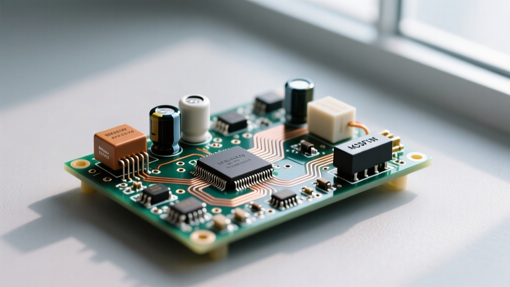
The input resistance of a non-inverting op-amp circuit is defined by the op-amp's internal common-mode input impedance, typically ranging from 1 MΩ in standard BJT designs up to 10¹² Ω (1 Teraohm) in CMOS or JFET architectures. Because the input signal connects directly to the non-inverting (+) terminal, there is no "virtual ground" pulling current from the source. This makes the non-inverting topology the go-to choice for buffering high-impedance sensors like piezoelectric pickups, pH probes, or electret microphones. Selecting the right semiconductor topology ensures your source signal isn't loaded down, preserving both amplitude and high-frequency bandwidth.
Op-Amp Pinout, Symbol, and the Non-Inverting Topology
Before wiring any circuit, you need to understand the physical package and the schematic symbol. The most common hobbyist and prototyping op-amp package is the 8-pin DIP (Dual In-line Package) or SOIC. While dual op-amps like the LM358 or TL072 are industry standards, their pinouts follow a strict convention:
- Pin 1: Output A
- Pin 2: Inverting Input A (-)
- Pin 3: Non-Inverting Input A (+)
- Pin 4: V- (Negative Supply or Ground)
- Pin 5: Non-Inverting Input B (+)
- Pin 6: Inverting Input B (-)
- Pin 7: Output B
- Pin 8: V+ (Positive Supply)
In schematic diagrams, the op-amp symbol is a triangle pointing right. The non-inverting input is marked with a plus (+) sign, and the inverting input is marked with a minus (-) sign. In a non-inverting configuration, your input signal is routed to the (+) terminal. The feedback network—usually a voltage divider consisting of two resistors—is connected from the output back to the (-) terminal. Because the input signal never passes through the feedback network, the circuit's input resistance is effectively just the intrinsic input resistance of the (+) terminal itself. For a deeper look at internal transistor models, the Texas Instruments Op-Amp Overview provides excellent architectural breakdowns.
Input Resistance Specs Across Op-Amp Topologies
Not all op-amps are created equal. The input stage transistor technology dictates the input resistance and the input bias current (the tiny amount of current the op-amp draws from your source to bias its internal transistors). If your source has a high output impedance, even a few nanoamps of bias current will create a voltage drop, causing DC offset errors.
| Input Topology | Example Part | Typical Input Resistance | Input Bias Current (Ib) | Best Use Case |
|---|---|---|---|---|
| Bipolar (BJT) | LM358 / NE5532 | 1 MΩ to 10 MΩ | 20 nA to 500 nA | General purpose, low-impedance sources, audio line-level |
| JFET | TL072 / LF353 | 10¹² Ω (1 TΩ) | 5 pA to 50 pA | Audio preamps, high-impedance instrument buffers |
| CMOS | MCP6002 / TLC27L2 | 10¹² Ω (1 TΩ) | 1 pA to 10 pA | Battery-powered sensors, pH meters, photodiode amps |
| Precision Bipolar | OPA227 / LT1028 | 1 GΩ to 10 GΩ | 1 nA to 10 nA | Ultra-low noise applications, strain gauges, thermocouples |
Designing the Application Circuit: Biasing and Component Selection
Let's build a complete, real-world application circuit: an AC-coupled non-inverting amplifier for an electret microphone capsule, targeting a voltage gain of 11. We will use the MCP6002 (a CMOS dual op-amp) powered by a single 5V supply.
Component Values and Wiring
- Op-Amp: MCP6002 (U1). Pin 8 to +5V, Pin 4 to GND.
- Input Coupling: 1 µF film capacitor in series with the microphone signal to block DC.
- Input Bias Resistor (R_bias): 1 MΩ resistor from the non-inverting input (Pin 3) to a 2.5V reference (created by a voltage divider from the 5V rail). This is critical: CMOS inputs draw virtually zero current, but they still require a DC path to a reference voltage to establish the common-mode operating point. Without R_bias, the input floats, and the output will rail.
- Feedback Network: Connect R_f (100 kΩ) from the output (Pin 1) to the inverting input (Pin 2). Connect R_g (10 kΩ) from Pin 2 to the 2.5V reference.
- Output Coupling: 10 µF capacitor in series with the output to block the 2.5V DC offset before sending the signal to an ADC or audio jack.
Gain Calculation
The closed-loop voltage gain (A_v) of a non-inverting amplifier is calculated as:
A_v = 1 + (R_f / R_g)
Using our values: A_v = 1 + (100,000 / 10,000) = 1 + 10 = 11 V/V.
Because the MCP6002 has an input resistance of >10¹² Ω, the 1 MΩ bias resistor actually dominates the circuit's input impedance. The source (the microphone) "sees" a 1 MΩ load, which is perfectly adequate for audio frequencies without attenuating the low-end response. For a comprehensive guide on calculating bias networks for single-supply designs, the All About Circuits semiconductor textbook offers excellent foundational math.
Safe Default Part Numbers and Operation Regions
When stocking your lab or designing a production board, you need reliable, multi-sourced "safe default" op-amps. Here are the three workhorses you should keep in your bin, along with their operational limits.
| Part Number | Topology | Supply Voltage Range | Quiescent Current (Iq) | Output Short-Circuit Current |
|---|---|---|---|---|
| LM358 | Bipolar (BJT) | 3V to 32V (Single) or ±1.5V to ±16V | 0.7 mA per amp | ~40 mA (Continuous) |
| TL072 | JFET | 7V to 36V (Single) or ±3.5V to ±18V | 1.4 mA per amp | ~25 mA (Continuous) |
| MCP6002 | CMOS | 1.8V to 6.0V (Single only) | 100 µA per amp | ~25 mA (Continuous) |
Understanding Operation Regions
An op-amp behaves very differently depending on where it sits on its transfer curve. Knowing these regions is vital for debugging.
| Operation Region | V_in Differential (V+ minus V-) | V_out State | Typical Behavior & Thermal Notes |
|---|---|---|---|
| Linear Active | ~0V (Virtual Short) | Between V- and V+ rails | Normal amplification. Feedback forces V- to match V+. Device runs cool. |
| Positive Saturation | V+ > V- by >1 mV | Pinned near V+ rail (V+ - 1.5V) | Open-loop or overdriven. Output transistors fully on. Mild heating if sourced into a low impedance. |
| Negative Saturation | V- > V+ by >1 mV | Pinned near V- rail (or GND) | Open-loop or overdriven. Output transistors fully on. LM358 can swing to within 20mV of true ground. |
| Short-Circuit Protection | Any | Forced to 0V / Current Limited | Internal thermal shutdown or current limiting engages. Die temperature spikes rapidly; prolonged shorts destroy the part. |
Failure Modes and Multimeter Testing
Op-amps are generally robust, but they do fail, usually due to Electrical Overstress (EOS) or Electrostatic Discharge (ESD). The most common failure mode in high-impedance non-inverting circuits is the destruction of the internal input protection diodes. If a user hot-plugs a cable carrying a voltage higher than the op-amp's supply rail, the protection diodes conduct heavily to clamp the voltage. If the current isn't limited by an external series resistor, the diode junction melts, creating a permanent low-resistance short to the supply rail. Your 1 TΩ input resistance instantly drops to a few hundred ohms, killing the signal.
How to Test an Op-Amp with a Digital Multimeter (DMM)
If you suspect a blown input stage on a non-inverting circuit, follow this diagnostic sequence:
- De-energize and Isolate: Remove power from the circuit. If testing in-circuit, be aware that parallel feedback resistors will skew your readings. Desoldering the chip or lifting the input pin is ideal for accurate measurements.
- Diode Test Mode (Input Protection Check): Set your DMM to diode-test mode. Place the red probe on the non-inverting input pin and the black probe on the V- (ground) pin. You should read a standard silicon diode drop (0.6V to 0.7V). Reverse the probes; it should read "OL" (Open Line). If you read a dead short (0.00V) or a very low resistance in both directions, the internal ESD diode has melted. The chip is dead.
- Power-On Virtual Short Check: Reapply power. Set the DMM to DC Volts. Measure the voltage at the non-inverting input (+). Then measure the voltage at the inverting input (-). In a properly functioning linear circuit, the op-amp's open-loop gain forces these two pins to the exact same voltage (the "virtual short"). If Pin 3 reads 2.50V and Pin 2 reads 2.50V, the feedback loop is intact. If Pin 2 is stuck at 0V while Pin 3 is at 2.5V, the output stage is likely blown or the feedback resistor is open.
- Input Bias Current Verification: If the circuit works but has a massive DC offset error, your input bias current might be too high for your source. Temporarily insert a 1 MΩ resistor in series with your signal source. Measure the DC voltage drop across this resistor with your DMM. Using Ohm's Law (I = V/R), a 5mV drop across 1 MΩ indicates an input bias current of 5 nA. If your application requires lower bias, swap the BJT op-amp for a CMOS alternative.
By matching the correct semiconductor topology to your source impedance and implementing proper DC biasing and protection networks, you can fully leverage the massive input resistance of the non-inverting op-amp configuration without falling victim to common loading and failure pitfalls.