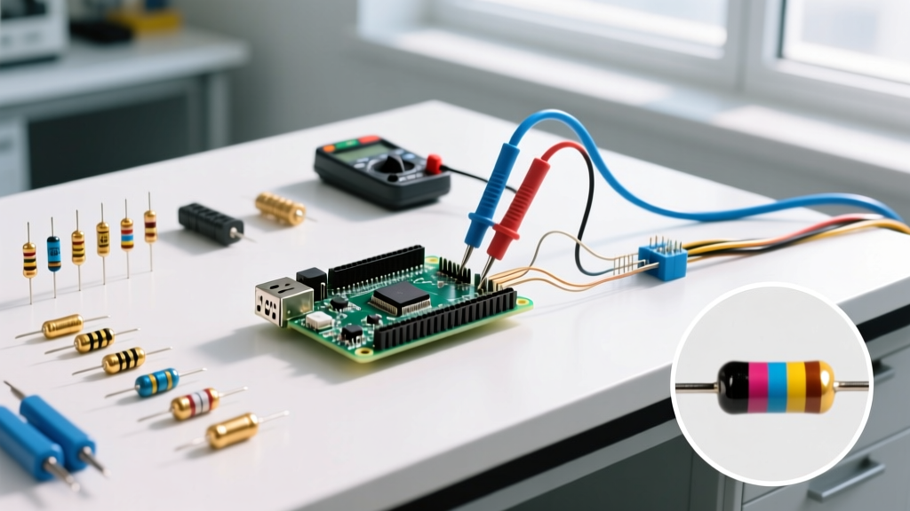

The unit of measurement for electrical resistance is the ohm (Ω), named after German physicist Georg Simon Ohm. In practical terms, one ohm is defined as the resistance that allows exactly one ampere of current to flow when one volt of electrical potential is applied across it (R = V/I). While textbooks stop at the math, bench and jobsite work requires you to translate that definition into physical troubleshooting. Whether you are checking a 10kΩ pull-up resistor on an ESP32 breadboard or verifying a 120V baseboard heater element, knowing what the ohm means is only half the battle. The other half is knowing how to extract an accurate measurement, interpret the numbers, and avoid the parasitic errors that ruin your data.
This guide moves past abstract theory into decision-forward test techniques, giving you exact meter setups, expected numerical baselines, and a troubleshooting decision tree to isolate faults.
The Ohm in Practice: Scale and Context
Resistance spans massive orders of magnitude. Misunderstanding the scale is the root of most diagnostic errors. A digital multimeter (DMM) will display values in ohms (Ω), kilohms (kΩ), or megohms (MΩ).
- Milliohms (mΩ): Used for wire continuity, shunt resistors, and busbar joints. A 10-foot run of 12 AWG copper wire should measure roughly 0.016Ω at 20°C.
- Ohms (Ω) to Kilohms (kΩ): The domain of standard electronic components (pull-downs, current-limiting resistors) and heating elements. A standard LED current-limiting resistor might be 220Ω; a 1500W space heater element is roughly 9.6Ω.
- Megohms (MΩ): Used for insulation resistance and high-impedance sensor circuits. A healthy motor winding to ground should read >1 MΩ (often >100 MΩ on a megohmmeter).
Multimeter Setup for Resistance Testing
Before touching a single probe to a circuit, configure your meter correctly. An improper setup yields phantom readings or blown internal fuses.
- De-energize the Circuit: Resistance is measured using the meter's internal battery to push a small test current through the component. External voltage will corrupt the reading and can destroy the meter's ADC.
- Dial Position: Turn the dial to the Omega (Ω) symbol. If your meter has manual ranging, select a range higher than your expected value (e.g., the 20kΩ setting for a 10kΩ resistor).
- Lead Jacks: Plug the black lead into the COM (Common) jack. Plug the red lead into the V/Ω (Volts/Ohms) jack. Never leave the red lead in the Amps (A or mA) jack when measuring resistance; this creates a dead short across your component when powered.
- Verify the Meter: Touch the probe tips together. The display should read between 0.0Ω and 0.3Ω. Separate them; the display should read 'OL' (Overload/Open Loop).
Probe Placement and Expected Readings
Probe placement dictates accuracy. For discrete components, place one probe on each lead of the component. Ensure your fingers are not touching the metal probe tips or the component leads simultaneously—your body has a resistance of roughly 50kΩ to 1MΩ, which will create a parallel circuit and artificially lower the reading of high-value resistors.
Use the table below as a baseline for what a numerically 'good' reading looks like versus a failed state.
| Component / Test Point | Expected 'Good' Reading | 'Bad' Reading & Failure Mode |
|---|---|---|
| 10kΩ Pull-up Resistor (Breadboard) | 9.50kΩ to 10.50kΩ (5% tolerance) | OL (Open/broken film) or < 1kΩ (Shorted/burned) |
| 12 AWG Copper Wire (10 ft run) | 0.01Ω to 0.03Ω | > 0.50Ω (Strand break or terminal corrosion) |
| 120V / 1500W Heating Element | 9.0Ω to 10.5Ω (Calculated: V²/W) | OL (Element snapped/burned out internally) |
| Small 12V DC Motor Windings | 2.0Ω to 15.0Ω | 0.00Ω (Commutator short) or OL (Brush failure) |
| GFCI Receptacle Ground Path | < 0.50Ω to grounding rod | > 5.0Ω (Poor soil contact or broken bond) |
Decision Tree: Troubleshooting Resistance Readings
When your meter displays an unexpected value, follow this decision path to isolate the fault. Do not guess; trace the logic.
| Symptom on DMM | Immediate Check | If Check Passes / Fault Confirmed | Concrete Action / Part Pick |
|---|---|---|---|
| Displays 'OL' (Open) | Verify probes are making solid metal-to-metal contact. Scrape off oxidation. | If still OL, the internal conductive path is broken. | Replace component. For standard 1/4W through-hole needs, swap with a Yageo CFR-25JR-52-10K (10kΩ 5% carbon film). |
| Displays 0.00Ω or near-zero | Is the component still soldered in-circuit? Desolder one leg to remove parallel paths. | If still 0.00Ω out-of-circuit, the component has suffered a catastrophic internal short. | Inspect PCB for solder bridges. If clean, discard component and check upstream voltage regulators for overvoltage damage. |
| Reading drifts continuously | Are you holding the metal tips? Are the probes in a high-vibration area? | If hands are clear, thermal EMF (Seebeck effect) or a failing carbon track is causing drift. | Clean probe tips with isopropyl alcohol. If drift persists on a potentiometer, replace with a Bourns 3296W cermet trimpot for better thermal stability. |
| Reading is lower than expected | Is the component isolated from the rest of the circuit? | If in-circuit, parallel semiconductor paths are dragging the value down. | Lift one leg of the component. If the reading normalizes, the component is fine; the circuit design is just loading it. |
Common Mistakes That Give Misleading Ohm Readings
Even with a high-end meter, operator error will ruin your data. Avoid these three bench and jobsite traps:
- Measuring In-Circuit: A 10kΩ resistor soldered across a microcontroller's VCC and GND pins will rarely read 10kΩ. The internal impedance of the voltage regulator, decoupling capacitors, and silicon junctions create parallel resistance paths. Always isolate at least one leg of the component from the circuit before measuring.
- The 'Finger Parallel' Error: When measuring a 1MΩ bleeder resistor on a power supply, holding the metal probe tips with your bare hands puts your body resistance in parallel with the resistor. If your skin resistance is 800kΩ, the meter will display roughly 444kΩ instead of 1MΩ. Use alligator clips or probe hooks for high-impedance measurements.
- Ignoring Thermal EMF in Milliohm Measurements: If you are measuring a 50mΩ shunt resistor and the solder joints are at different temperatures, the thermocouple effect generates a tiny DC voltage (microvolts). This voltage opposes or aids the DMM's test current, causing the reading to jump or show a negative resistance value. Let the board reach thermal equilibrium before measuring sub-ohm values.
Safety Categories (CAT Ratings) for Resistance Testing
Because resistance must be measured on de-energized circuits, many assume safety ratings do not matter. This is a fatal assumption. If you accidentally leave a circuit live, or if a transient voltage spike occurs while your probes are connected, your meter must be able to contain the arc.
Select your meter's CAT rating based on the environment, not just the task:
- CAT I: Protected electronics, bench power supplies, and low-voltage DC systems (Arduino, ESP32, 12V solar). An un-rated hobbyist meter is acceptable here.
- CAT II: Single-phase receptacles and plug-in appliances (120V/240V). Required for testing household heating elements, dryer thermostats, and appliance motors.
- CAT III: Three-phase distribution, fixed motor loads, and hardwired HVAC systems. This is the minimum rating you should own if you do any residential or commercial electrical troubleshooting.
- CAT IV: Service entrance panels, utility meters, and underground vaults. Reserved for licensed electricians and utility workers.
The Definitive Pick: If you are moving beyond the breadboard and need to measure resistance on HVAC contactors, hardwired appliances, or subpanel feeders, stop relying on $20 un-rated import meters. The default, concrete recommendation for 90% of prosumers and tradesmen is the Fluke 117 True-RMS Multimeter. It carries a CAT III 600V / CAT IV 300V safety rating, features VoltAlert (non-contact voltage detection built into the tip to prevent the 'live circuit' mistake before you switch to ohms), and has a low-impedance mode to prevent ghost voltage readings. For pure bench electronics (CAT I), the Brymen BM235 offers superior milliohm resolution and build quality at half the price.


