
The LED Light Semiconductor: Beyond the Bulb to the Die
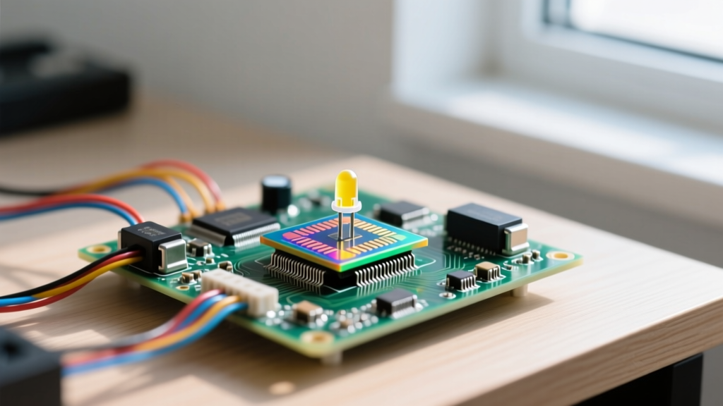
When we talk about LED lighting on the jobsite, we usually focus on the fixture, the lumen output, or the color temperature. But the actual behavior of the circuit is entirely dictated by the LED light semiconductor — the microscopic die sitting inside the package. Most white LEDs use an Indium Gallium Nitride (InGaN) semiconductor that emits blue light, which then passes through a yellow cerium-doped YAG phosphor to create white light. Red and amber fixtures typically rely on Aluminum Indium Gallium Phosphide (AlInGaP).
Unlike a tungsten filament, which acts as a relatively linear resistor, the LED light semiconductor has an exponential voltage-current (V-I) curve. A tiny increase in forward voltage ($V_f$) results in a massive spike in forward current ($I_f$). This non-linear behavior is why you cannot wire an LED die directly to a constant-voltage AC or DC source without a driver; it would experience thermal runaway and destroy itself in milliseconds.
Circuit Impact Math: Inrush, Power Factor, and the Driver
Because the semiconductor requires precise current regulation, we use LED drivers. But the driver's internal topology introduces two major circuit impacts that trip up standard residential and commercial wiring calculations: inrush current and power factor.
Inrush Current and Breaker Nuisance Tripping
Most constant-voltage LED drivers use a bulk electrolytic capacitor on the input side to smooth the rectified AC waveform. When you flip the wall switch, that empty capacitor looks like a dead short to the AC line for the first few microseconds. The inrush current ($I_{inrush}$) is limited only by the equivalent series resistance (ESR) of the capacitor and the trace resistance.
The math is straightforward: $I_{peak} = \frac{V_{peak}}{R_{ESR}}$. On a 120V nominal line, the peak voltage is roughly 170V. If the driver's ESR is 2 ohms, the inrush spike is 85 Amps. While this lasts less than a half-cycle (8.3ms), it is enough to trip the magnetic instantaneous release on a standard thermal-magnetic breaker if you have too many fixtures on one switch.
- The Fix: Never size branch circuits based solely on steady-state wattage. A 15A breaker allows 12A continuous. If each 15W fixture draws 0.125A steady-state, you might think you can put 90 fixtures on one switch. In reality, the combined inrush of 90 drivers will instantly trip a C-curve breaker. Limit standard residential LED branches to 10–14 fixtures per switch leg to stay below the magnetic trip threshold.
Power Factor (PF) and Driver Sizing
Cheap, low-wattage drivers often use a capacitive dropper circuit, yielding a terrible Power Factor (PF) of 0.4 to 0.5. This means the apparent power (VA) drawn from the panel is more than double the real power (Watts) consumed by the semiconductor. High-quality commercial drivers use Active Power Factor Correction (PFC), pushing PF above 0.9.
Which driver for this fixture count? Always sum the maximum wattage of your semiconductor modules and add a 20% headroom buffer. If you are wiring six 10W downlights (60W total), do not buy a 60W driver. Buy a 75W constant-current driver (like the Mean Well HLG-80H series). Running a driver at 100% load reduces its internal capacitor lifespan and generates excess heat.
Dimmer Compatibility: Matching the Semiconductor's V-I Curve
Dimmers were originally designed for incandescent bulbs. Standard TRIAC (leading-edge) dimmers work by chopping off the front half of the AC sine wave. However, TRIACs require a minimum 'holding current' to stay latched. Because the LED light semiconductor is so efficient, it draws very little current, causing the TRIAC to drop out mid-cycle. This results in the dreaded 120Hz strobe flicker.
To fix this, you must use a trailing-edge (ELV) dimmer. Trailing-edge dimmers use MOSFETs or IGBTs instead of TRIACs. They chop the back half of the sine wave and do not require a high minimum holding current. However, you still must check the dimmer's minimum load rating.
Lumens, Watts, and Efficacy Context
When calculating your total load for dimmer sizing, you need to know exactly how many watts your semiconductor is pulling to achieve the desired light level. The table below provides real-world equivalencies, emphasizing the efficacy (lumens per watt) that dictates your circuit load.
| Light Source Technology | Semiconductor / Element | Typical Wattage | Output (Lumens) | Efficacy (lm/W) |
|---|---|---|---|---|
| Incandescent | Tungsten Filament | 60W | 800 lm | 13.3 lm/W |
| Halogen | Tungsten + Halogen Gas | 43W | 750 lm | 17.4 lm/W |
| Standard LED (A19) | InGaN Die + Phosphor | 9W | 800 lm | 88.8 lm/W |
| High-Efficacy Commercial | Optimized InGaN Die | 6W | 900 lm | 150.0 lm/W |
Source context: Efficacy data aligns with U.S. Department of Energy Solid-State Lighting benchmarks for commercial-grade phosphor-converted white LEDs.
Why Flicker Happens and the Fix
If you have the right trailing-edge dimmer and the correct minimum load, but the fixture still flickers at the bottom 10% of the dimming range, the issue is a mismatch between the dimmer's internal bleed circuit and the driver's input capacitance.
The Fix: Install a bypass resistor (such as the Lutron LUT-MLC) across the line and load at the fixture. This provides a dummy resistive load that keeps the dimmer's internal electronics stable. For new construction, bypass phase-cut dimmers entirely and specify 0-10V or PWM dimmable drivers, which control the semiconductor current via a low-voltage DC signal rather than chopping the AC mains.
LED Light Semiconductor FAQ
Why does my LED light semiconductor flicker when dimmed low?
Flicker at low dimming levels is almost always caused by the driver failing to maintain a continuous current to the semiconductor die. In phase-cut dimming, the chopped AC wave leaves 'dead time' where voltage drops to zero. If the driver's internal bulk capacitor is too small to bridge this dead time, the current to the InGaN die drops below its minimum threshold, and the light extinguishes for a fraction of a millisecond. This repeats 120 times a second, creating visible flicker. Upgrading to a driver with a larger smoothing capacitor or switching to a 0-10V analog dimming topology eliminates this dead-time dropout.
How many LED light semiconductors can I put on a single 15-amp breaker?
Do not calculate this using steady-state wattage; calculate it using inrush current. A standard 15A breaker is rated for 12A continuous load. If you are using high-quality commercial fixtures with active PFC and low-inrush drivers (e.g., 20A inrush per fixture), you can safely wire up to 14 fixtures on a 15A branch. If you are using cheap, high-inrush consumer fixtures (which can spike to 60A+ per driver), limit the branch to 8 fixtures. Exceeding these limits will cause the breaker's magnetic trip mechanism to nuisance-trip the moment you flip the switch, even though the steady-state draw is only 2 Amps. For detailed breaker trip curves, refer to Illuminating Engineering Society (IES) guidelines on SSL branch circuit sizing.
Does the LED light semiconductor type affect color shifting over time?
Yes, drastically. The semiconductor chemistry dictates the degradation curve. InGaN (blue-pump) white LEDs rely on a yellow phosphor layer. Over thousands of hours, the heat generated at the semiconductor junction degrades the silicone binder holding the phosphor, causing it to yellow. This shifts the correlated color temperature (CCT) downward, making a 4000K light look like 3200K. Conversely, AlInGaP (red/amber) semiconductors do not use phosphors, but their internal quantum efficiency drops rapidly if the junction temperature exceeds 85°C, leading to a permanent loss of lumen output without a massive color shift. Always check the manufacturer's LM-80 and TM-21 reports to predict long-term color stability.