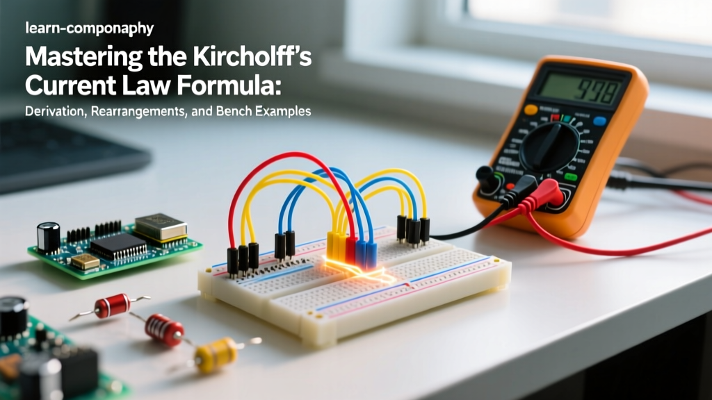

The Kirchhoff's Current Law (KCL) formula dictates that the algebraic sum of all currents entering and exiting a node must equal zero. In practical bench terms: what goes in must come out. Whether you are sizing traces on a custom PCB or debugging a parasitic drain on a 12V solar battery bank, KCL is the foundational accounting principle of electrical charge. This guide breaks down the exact mathematics, rearranged forms, and physical limitations of the formula, moving past textbook abstractions into real-world workbench applications.
The Core Kirchhoff's Current Law Formula and Symbol Definitions
At its core, KCL is an expression of the conservation of charge. A node—a point where two or more circuit elements connect—cannot store, create, or destroy electrons. The standard algebraic representation of the Kirchhoff's Current Law formula is:
Σk=1n Ik = 0
Alternatively, for rapid bench calculations, we separate the directions into an equality:
Iin(total) = Iout(total)
| Symbol | Definition | Standard Unit | Practical Context |
|---|---|---|---|
| Σ | Summation operator | N/A | Adds all branch currents together algebraically. |
| k | Index variable | N/A | Identifies the specific branch (e.g., Branch 1, Branch 2). |
| n | Total number of branches | N/A | The total count of wires/traces connected to the node. |
| Ik | Current in branch k | Amperes (A) | Positive (+) for current entering, negative (-) for exiting (by standard convention). |
| Iin | Sum of entering currents | Amperes (A) | Current flowing from a higher potential source into the node. |
| Iout | Sum of exiting currents | Amperes (A) | Current flowing from the node toward a lower potential or ground. |
Rearranged Forms: Solving for Any Branch Current
On the workbench, you rarely need the sum to equal zero; you need to find an unknown branch current. By assigning entering currents as positive and exiting currents as negative, we can rearrange the formula to isolate any unknown variable. Assume a node with four branches: $I_1$ and $I_2$ entering, $I_3$ and $I_4$ exiting.
- Solving for an unknown entering current (e.g., $I_1$):
I1 = I3 + I4 - I2 - Solving for an unknown exiting current (e.g., $I_4$):
I4 = I1 + I2 - I3 - General isolation for any branch 'x':
Ix = Σ Iknown_in - Σ Iknown_out (excluding x from the sums, adjusting sign based on assumed direction).
Assumptions, Boundaries, and Unit Traps
The Kirchhoff's Current Law formula is not a universal law of physics; it is a consequence of the lumped element model. Understanding when it applies—and when it breaks—is what separates a hobbyist from an engineer.
When the Formula Applies (and Its Assumptions)
KCL assumes that no charge accumulates at the node itself. It treats the node as an ideal, zero-dimensional geometric point. This holds true for DC circuits and low-frequency AC circuits where the physical dimensions of the circuit are vastly smaller than the wavelength of the signal. According to Georgia State University's HyperPhysics, as long as the circuit operates well below RF frequencies, the parasitic capacitance of the node is negligible, and charge conservation strictly applies to the connected components.
Which Unit Mistakes Break It
The most common point of failure in KCL calculations is unit mismatch. The formula demands uniform units. If you mix Amperes and milliamperes without converting, the math collapses.
The Trap: Iin = 2A. Iout1 = 500mA. Find Iout2.
The Mistake: 2 - 500 = -498A. (A physically impossible answer for this circuit).
The Fix: Convert 500mA to 0.5A. 2A - 0.5A = 1.5A.
When solving for an unknown, sanity-check your result against the physical domain. Signal and logic nodes (I2C, SPI, GPIO) typically operate in the μA to low mA range. Power distribution nodes (motor drivers, LED strips, inverters) operate in the 1A to 100A+ range. If your KCL calculation for an ESP32 GPIO node yields 4.2A, you have either made a decimal error or your microcontroller is actively venting magic smoke.
Solved Problems: From Textbook Nodes to the Workbench
Let's apply the formula to two distinct scenarios, tracking units at every step to prevent the errors mentioned above.
Problem 1: The Solar DC Distribution Block
Scenario: A 12V DC distribution block acts as a single node. A solar charge controller feeds power into the block. Three loads are connected: a 12V water pump, a lighting relay, and a battery monitor shunt. We need to find the exact current charging the battery.
- Isolar (entering) = 42.5 A
- Ipump (exiting) = 18.2 A
- Ilights (exiting) = 4.8 A
- Ishunt (exiting to battery) = ?
Step-by-Step Solution:
- State the formula: Iin(total) = Iout(total)
- Substitute knowns: 42.5 A = 18.2 A + 4.8 A + Ishunt
- Sum the known exiting currents: 18.2 A + 4.8 A = 23.0 A
- Rearrange for Ishunt: Ishunt = 42.5 A - 23.0 A
- Calculate: Ishunt = 19.5 A
Bench check: A 19.5A charging current is perfectly realistic for a 200W-300W solar array on a 12V nominal system (approx 14.4V charging voltage).
Problem 2: Microcontroller GPIO LED Node
Scenario: An ESP32 GPIO pin (configured as an output, driving LOW) is connected to a node. A 1kΩ pull-up resistor connects the node to 3.3V. An LED with a forward voltage of 2.0V and a 220Ω current-limiting resistor connects the node to ground. We need to find the current sinking into the ESP32 GPIO pin.
- Ipullup (entering from 3.3V rail) = (3.3V - 0V) / 1000Ω = 3.3 mA (Assuming GPIO is at ~0V when LOW)
- ILED (exiting to ground) = (0V - 2.0V) is invalid; current flows from node to ground. Wait, if GPIO is LOW (0V), the LED path is reverse biased or off if the anode is at the node and cathode to ground. Let's correct the circuit topology for a standard sink: 3.3V -> Resistor -> LED -> Node -> GPIO.
Corrected Topology: 3.3V source feeds a 220Ω resistor, then an LED (Vf=2.0V), arriving at the Node. The Node connects to the ESP32 GPIO (LOW, ~0.1V). - Isource (entering node from LED) = (3.3V - 2.0V - 0.1V) / 220Ω = 1.2V / 220Ω = 5.45 mA
- IGPIO (exiting node into chip) = ?
Step-by-Step Solution:
- State the formula: Σ Ik = 0 → Isource - IGPIO = 0
- Substitute knowns: 5.45 mA - IGPIO = 0
- Rearrange: IGPIO = 5.45 mA
- Calculate: IGPIO = 5.45 mA
Bench check: The ESP32-WROOM-32 datasheet specifies a maximum GPIO sink current of 28 mA. At 5.45 mA, the pin is operating safely within its linear region.
Real-World Scenario Walkthrough: The Melted Breadboard Node
Understanding the math is only half the battle. KCL tells you how much current must flow through a node; physics dictates whether the physical material can survive it. Here is a teardown of a common, destructive workbench mistake.
The Setup
A maker is prototyping a robotics chassis. They use a single solderless breadboard to distribute power from a 12V 5A DC barrel jack. The positive rail acts as a single massive KCL node. Connected to this node are:
- A 12V DC motor (via a motor driver).
- A 5V step-down buck converter feeding the logic circuits.
- A high-power 12V LED strip for status indication.
The Numbers
Let's apply the Kirchhoff's Current Law formula to the positive rail node during a stall condition:
- ILED = 1.8 A (constant)
- IBuck = 0.5 A (logic load)
- IMotor_Stall = 4.2 A (motor jams, drawing stall current)
Using KCL: ISource = 1.8 A + 0.5 A + 4.2 A = 6.5 A.
The Outcome
The 12V 5A power supply's over-current protection (OCP) should have tripped at 5.5A. However, cheap bench supplies often have a slow OCP response or are rated for 'peak' rather than continuous current. The supply pushed 6.5A through the breadboard's internal metal clips for approximately 15 seconds before the thermal mass of the plastic housing reached its ignition/melting point. The breadboard warped, the plastic melted around the power rails, and the node was permanently destroyed.
What Went Wrong (The Engineering Post-Mortem)
- Ignored Component Ratings: Standard solderless breadboards (like the common MB-102) are rated for a maximum of 1A to 2A per contact strip. The maker treated the breadboard rail as an ideal, zero-resistance KCL node.
- Parasitic Resistance: The breadboard clips have a contact resistance of roughly 0.1Ω to 0.5Ω per jump. At 6.5A, P = I²R means the node was dissipating over 20 Watts of heat purely in the metal clips.
- The Fix: High-current nodes must bypass the breadboard entirely. The maker should have used a dedicated PCB terminal block, a XT60 connector splitter, or soldered the high-current paths directly, using the breadboard strictly for the <1A logic signals.
As detailed in All About Circuits' DC textbook chapter on KCL, the law assumes ideal conductors. In reality, every node has resistance, thermal limits, and parasitic inductance. Use the Kirchhoff's Current Law formula to balance your circuit's accounting, but always cross-reference the result against the ampacity and thermal derating charts of your physical wiring and connectors. For further reading on managing power distribution nodes safely, review the Electronics Tutorials guide on Kirchhoff's Laws to solidify your grasp on nodal analysis.


