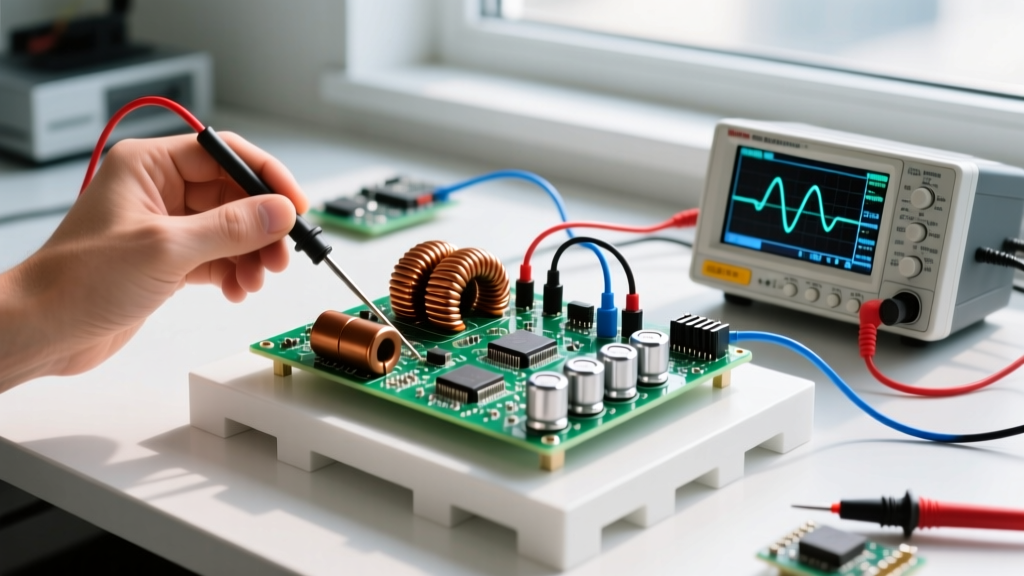
The relationship between an inductor and voltage is not static; it is entirely dynamic and governed by the rate of current change. When selecting an inductor for power conversion, relay driving, or filtering, the primary failure point is rarely the inductance value itself—it is the voltage spike (back-EMF) generated when current is interrupted, or the voltage drop caused by DC resistance (DCR). To design a robust circuit, you must size the coil to handle both the steady-state voltage drop and the transient voltage spikes, while pairing it with the correct flyback protection.
The Core Equation: How Inductor and Voltage Interact
The fundamental law dictating this behavior is Faraday's law of induction, expressed as:
V = L × (di/dt)
Where V is the induced voltage, L is inductance in Henries, and di/dt is the rate of change of current over time. Think of an inductor as a heavy mechanical water wheel in a pipe. Voltage is the water pressure required to get the wheel spinning (current flowing). Once spinning, the wheel has momentum. If you suddenly slam a valve shut (opening a switch or turning off a MOSFET), the water wheel's momentum forces water against the closed valve, creating a massive, destructive pressure spike. In electronics, this is water hammer, or back-EMF.
Conversely, in steady-state DC, an inductor acts merely as a resistor. The voltage drop across it is simply Ohm's law: Vdrop = I × DCR. If your inductor has a DCR of 50mΩ and carries 5A, it drops 0.25V and dissipates 1.25W as heat. Sizing an inductor means balancing the inductance needed for your switching frequency against the DCR and saturation current limits.
Inductor Construction and Voltage Tolerance Matrix
Different core materials and winding techniques dictate how well an inductor handles voltage stress, heat, and electromagnetic interference (EMI). Use this spec-sheet-table framework to match the physical construction to your circuit's voltage and current demands.
| Construction Type | Tolerance | Tempco (ppm/°C) | Typical Use | Voltage / Isolation Limit |
|---|---|---|---|---|
| Shielded Molded (e.g., Coilcraft MSS) | ±10% to ±20% | -100 to +100 | DC-DC Buck/Boost converters, high-frequency switching | High (Epoxy encapsulated, minimal arc-over risk) |
| Unshielded Drum (e.g., Bourns RLB) | ±10% to ±20% | Varies widely | Low-cost power supplies, relay coils, low-freq filtering | Medium (Exposed windings can arc at >500V spikes) |
| Toroidal (e.g., Bourns 2100 series) | ±15% to ±20% | Core dependent | High-current EMI filtering, audio crossovers, AC line | Very High (Thick enamel, high dielectric breakdown) |
| Multilayer Ceramic (e.g., Murata LQG) | ±2% to ±10% | +100 to +350 | RF matching, high-frequency signal filtering (<1A) | Low (Internal micro-arcing if subjected to high dV/dt) |
Decoding Physical Markings and Specs
When scavenging parts or verifying a BOM, you need to read the physical codes stamped on the component. Unlike resistors, inductor markings can be ambiguous. Here is how to decode the standard 3-digit and alphanumeric codes found on SMD and through-hole power inductors:
- The 'R' Decimal Marker: A code like 4R7 means 4.7µH. The 'R' acts as the decimal point. A code like R47 means 0.47µH.
- The 3-Digit Multiplier: For values 10µH and above, the first two digits are significant figures, and the third is the multiplier (number of zeros) in microhenries.
- 100 = 10 × 100 = 10µH
- 101 = 10 × 101 = 100µH
- 472 = 47 × 102 = 4700µH (4.7mH)
- Tolerance Letters: Usually trailing the numeric code.
- J = ±5%
- K = ±10%
- M = ±20% (Most common for power inductors)
Therefore, an SMD inductor stamped 470K is a 47µH coil with a ±10% tolerance. Always verify the datasheet for the specific manufacturer, as some RF inductors use picohenry (pH) or nanohenry (nH) base multipliers instead of microhenries.
Failure Modes: Visual Symptoms of Voltage Stress
When the voltage across an inductor exceeds its design limits, or when the current exceeds the core's magnetic capacity, the component fails. According to TI's application notes on inductor selection, ignoring saturation and voltage spikes leads to catastrophic system failure.
1. Core Saturation (The Invisible Killer)
What happens: The magnetic core reaches its flux density limit ($B_{max}$). The inductance drops to near zero, and the coil becomes a simple wire. Current spikes uncontrollably, destroying the driving MOSFET.
Visual Symptoms: The inductor itself may look perfectly fine initially. The visual evidence is usually found on the driving semiconductor—a cracked, exploded, or melted MOSFET/IC, and scorched PCB traces leading to the inductor.
2. Insulation Breakdown and Arc-Over
What happens: The back-EMF voltage spike exceeds the dielectric strength of the thin enamel coating on the copper windings, or arcs across the SMD pads.
Visual Symptoms: Look for 'corona rings' (white or grey powdery deposits) on toroidal cores, pitted or blackened SMD termination pads, or a distinct smell of ozone and burnt epoxy. Under magnification, you will see micro-craters in the wire enamel.
3. Thermal Runaway from DCR Losses
What happens: The RMS current exceeds the component's thermal rating, causing $I^2R$ heating that degrades the core's permeability and melts solder joints.
Visual Symptoms: Discolored (brown/yellow) PCB solder mask directly under the component, dull or crystallized solder joints, and a bulging epoxy casing.
Safe Substitution Rules for Missing Parts
When repairing a board or prototyping without the exact BOM part, you cannot simply swap any coil with the same microhenry rating. Follow these strict substitution rules to maintain the inductor and voltage balance:
- Inductance Value: For power conversion (buck/boost), a ±20% deviation is generally acceptable as the control loop will adjust the duty cycle. For RF filters or precision timing oscillators, you must match within ±5%.
- Saturation Current ($I_{sat}$): The substitute must have an $I_{sat}$ rating equal to or greater than the original. Never substitute a lower $I_{sat}$ part, or you risk immediate core saturation and switch failure.
- DC Resistance (DCR): Choose a substitute with a lower or equal DCR. A higher DCR will increase the steady-state voltage drop ($V = I imes DCR$), reducing efficiency and causing excess heat.
- Physical Footprint & Shielding: If replacing a shielded inductor with an unshielded one, ensure the new part is not placed within 5mm of sensitive analog traces or Hall-effect sensors, as the uncontained magnetic flux will induce voltage noise.
Decision Path: Picking Your Inductor and Protection
Stop guessing. Use this decision-tree-table to select the exact inductor topology and flyback diode for your specific application. This terminates the 'it depends' loop and gives you concrete part numbers to source.
| Application Scenario | Key Constraint | Inductor Pick (Concrete Part) | Flyback / Snubber Pick |
|---|---|---|---|
| DC-DC Buck Converter (e.g., LM2596, 500kHz+ switching) | High $di/dt$, needs low DCR, must not radiate EMI. | Coilcraft MSS1210-473KEB (47µH, Shielded, 8.6A $I_{sat}$) | Integrated in sync FET, or STMicro STPS2L30 (Schottky, 30V, 2A) for async. |
| Relay / Solenoid Driver (e.g., 12V automotive relay, low freq) | Massive back-EMF spike on turn-off, low switching frequency. | Bourns RLB9012-470KL (47µH, Unshielded drum, cheap, high surge) | 1N4007 (Standard rectifier, slow recovery is fine here, 1000V PIV). |
| High-Speed Signal / Snubber (e.g., Contact bounce suppression) | Needs to absorb high-frequency voltage ringing without saturating. | Wurth 74477420 (1mH, Shielded power, or use a Ferrite Bead like BLM21) | 1N4148 (Fast switching signal diode) in series with a 100Ω resistor. |
| AC Line EMI Filter (e.g., Mains input filtering, 50/60Hz) | High continuous AC voltage, requires strict isolation and safety ratings. | Bourns 2100-V-RC (Toroidal Common Mode Choke, high dielectric isolation) | Paired with X2/Y2 Safety Capacitors (e.g., KEMET PHE840) for line-to-ground. |
By respecting the physics of $V = L(di/dt)$ and matching the physical construction to your voltage environment, you eliminate the most common causes of power supply and driver failures. Always pair your chosen inductor with the correct flyback path, and verify your $I_{sat}$ margins on the bench before committing to a production run.