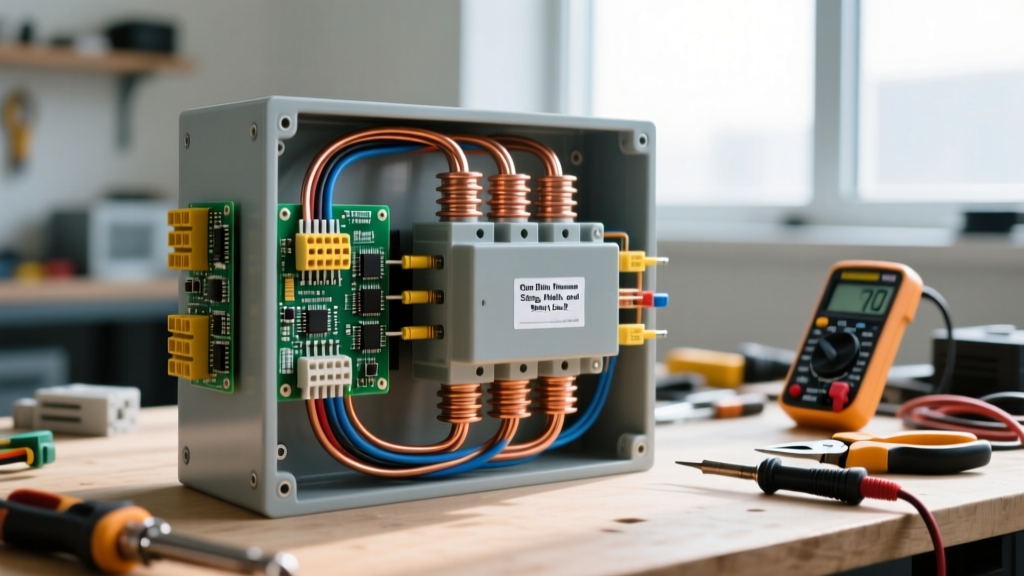
Electricity is the directed flow of free electrons through a conductive medium, driven by a difference in electrical potential (voltage). When you flip a switch, you aren't creating new electrons; you are applying an electromotive force that pushes the free electrons already present in the copper wire, transferring energy from the source to the load.
The Core Mechanism: Potential, Flow, and Resistance
To understand how electricity works in a physical circuit, you must separate the concept into three measurable properties: voltage, current, and resistance. According to foundational physics principles outlined by Georgia State University's HyperPhysics, these three variables are locked together by Ohm's Law (V = I × R).
The Water Analogy (Used Once): Imagine a pressurized water tank connected to a hose. Voltage (Volts) is the water pressure pushing outward. Current (Amps) is the actual volume of water flowing through the hose per second. Resistance (Ohms) is the diameter of the hose or a kink restricting the flow. If you increase the pressure (voltage) or widen the hose (lower resistance), more water flows (higher current).
What it changes in a real circuit: When electricity flows through a real installation, it changes electrical potential energy into other forms of energy: thermal energy (heat in a toaster), magnetic fields (torque in a motor), or photons (light in an LED). The physical copper wire itself does not change or degrade under normal conditions, but the energy state of the electrons shifts. Furthermore, because no conductor is perfect, the flow of electrons collides with the copper's atomic lattice, generating I²R (current squared times resistance) heat. This is why wires get warm under heavy loads.
Worked Example: Sizing a Branch Circuit for a 1500W Space Heater
Theory becomes critical when you need to select the right wire and breaker to prevent a fire. Let's calculate the requirements for a standard portable space heater.
Load: 1500 Watts | Source Voltage: 120V AC (Nominal) | Power Factor: 1.0 (Resistive load)
Step 1: Calculate the Base Current
Using the power formula P = V × I, we rearrange to solve for current: I = P / V.
1500W / 120V = 12.5 Amps.
Step 2: Apply the NEC Continuous Load Rule
Under NEC Article 210.20(A), if a load is expected to run for 3 hours or more (like a space heater on a cold night), you must multiply the base current by 125% to size the overcurrent protection.
12.5A × 1.25 = 15.625 Amps.
Step 3: Select Wire and Breaker
A standard 14 AWG copper wire is rated for 15 Amps in the 60°C column of NEC Table 310.16. Because 15.625A exceeds 15A, 14 AWG is illegal and unsafe for this continuous load. You must step up to 12 AWG copper wire, which is rated for 20 Amps (60°C column) or 25 Amps (75°C column). Consequently, you must protect this circuit with a 20-Amp breaker, not a 15-Amp breaker.
Where You Meet This in Practice
On the bench or the jobsite, the abstract flow of electrons manifests in very physical, measurable ways. Here is where the theory dictates your daily workflow:
- Voltage Drop on Long Runs: If you run 100 feet of 12 AWG wire to a shed and pull 15 Amps, the wire's inherent resistance (roughly 1.98 ohms per 1000 ft for solid copper) causes a voltage drop. Using V = I × R, the 200-foot round trip (hot and neutral) drops about 5.9 Volts. Your 120V source arrives at the shed as ~114V. Motors will run hotter and draw more current to compensate, which is why long runs require upsizing to 10 AWG or 8 AWG.
- Termination Torque and Heat: If you don't torque a breaker lug to the manufacturer's spec (e.g., 25 in-lbs for a standard Square D QO breaker), the microscopic air gaps increase the contact resistance. Under a 20A load, that high-resistance joint will generate localized heat, eventually melting the wire insulation and causing an arc fault.
- Measurement Technique: You cannot measure current by placing multimeter probes across a live outlet—that creates a dead short through the meter's shunt, resulting in a blown fuse or an arc flash. Current must be measured in series (breaking the circuit) or safely via a non-contact clamp meter (like the Fluke 117 or Klein CL800) which reads the magnetic field generated by the electron flow.
Common Confusions: What People Get Wrong
Misunderstanding how electricity works leads to dangerous assumptions in DIY wiring and electronics design. Let's clear up the most common myths.
Myth 1: "Current is used up by the load."
Current is not consumed; it is the energy (voltage potential) that is expended. If 10 Amps of current flows into a motor on the hot wire, exactly 10 Amps returns on the neutral wire. If the returning current is even slightly less than the outgoing current (e.g., 9.9A), that missing 0.1A is leaking to ground, which is exactly what a GFCI breaker detects to trip the circuit.
Myth 2: "Electrons travel through the wire at the speed of light."
The electromagnetic wave (the signal or energy) propagates through the dielectric material around the wire at a significant fraction of the speed of light. However, the actual physical electrons move incredibly slowly—a phenomenon called drift velocity. In a typical 12 AWG copper wire carrying 10 Amps of DC current, the electrons drift at roughly 0.1 millimeters per second. The light turns on instantly because the wire is already packed full of electrons; pushing one in at the switch instantly pushes one out at the bulb.
Myth 3: "Higher voltage is always more lethal."
Frequently Asked Questions
How does electricity work in a battery compared to a wall outlet?
A battery provides Direct Current (DC), where the electromotive force pushes electrons in a single, continuous direction from the negative terminal to the positive terminal through the external circuit. A wall outlet provides Alternating Current (AC), where the utility grid reverses the polarity of the voltage 60 times per second (60Hz in North America). In AC, the electrons simply vibrate back and forth in place, transferring energy via the changing electromagnetic field rather than making a complete journey from the power plant to your home.
How does electricity work when a circuit is open or switched off?
When a switch is open, the physical gap introduces infinite resistance into the circuit. The voltage (potential difference) is still present across the terminals of the open switch, acting like pressure against a closed valve. However, because the resistance is effectively infinite, Ohm's Law dictates that current flow drops to zero. No energy is transferred, and no work is done until the gap is bridged.
How does electricity work in a ground wire during a fault?
Under normal conditions, the bare copper or green equipment grounding conductor carries zero current. It sits at the same electrical potential as the earth. If a hot wire frays and touches the metal chassis of an appliance, the ground wire provides a deliberate, ultra-low-impedance path back to the main panel's neutral-ground bond. This massive, unrestricted flow of electrons creates a short circuit, instantly generating enough magnetic force to trip the breaker's thermal-magnetic mechanism in milliseconds, removing the shock hazard.
How does electricity work in an LED versus an incandescent bulb?
In an incandescent bulb, electricity works through thermal radiation: the current encounters high resistance in a thin tungsten filament, generating so much I²R heat (up to 4,500°F) that the metal glows white-hot, converting 90% of the energy into wasted heat and 10% into light. In an LED (Light Emitting Diode), electricity works through electroluminescence. Electrons cross a semiconductor p-n junction and drop into lower-energy "holes" in the crystal lattice, releasing their excess energy directly as photons. This solid-state process generates very little heat, making LEDs roughly 85% more efficient.