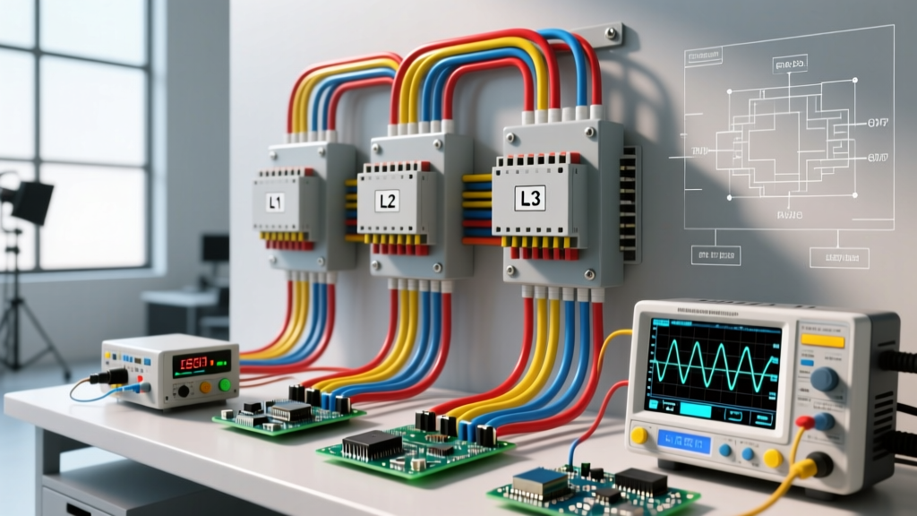
A harmonics filter is a tuned or broadband network of inductors and capacitors designed to shunt or block unwanted high-frequency current multiples from distorting the fundamental AC power waveform. When non-linear loads like variable frequency drives (VFDs), LED drivers, and switched-mode power supplies chop up the smooth 50/60Hz AC sine wave, they inject harmonic currents back into the grid. Installing a harmonics filter changes the real-world behavior of your installation by reducing Total Harmonic Distortion (THD), lowering the true RMS current, preventing neutral conductor overheating, and stopping transformers from prematurely failing due to eddy current losses.
The Anatomy of Waveform Distortion
To understand the filter, you must understand the distortion. A pure AC power system operates at a fundamental frequency (60Hz in North America, 50Hz in Europe). Non-linear loads do not draw current continuously throughout the voltage cycle; they draw it in sharp, abrupt pulses near the voltage peaks.
Using Fourier analysis, these jagged current pulses can be broken down into the fundamental 60Hz wave plus a series of integer multiples called harmonics. In three-phase systems, the even harmonics cancel out, leaving the odd harmonics: the 3rd (180Hz), 5th (300Hz), 7th (420Hz), 11th (660Hz), and so on. These high-frequency currents encounter higher impedance in cables and transformers, generating excessive heat (I²R losses scale with frequency due to the skin effect). A harmonics filter provides a low-impedance path to ground for these specific frequencies, or injects opposing currents to cancel them out.
The Common Confusion: Harmonics vs. EMI vs. PFC
On the jobsite, people frequently confuse a harmonics filter with other power conditioning equipment. Buying the wrong one will leave your THD untouched and your equipment at risk.
| Device | Target Frequency | Primary Function | What it DOES NOT fix |
|---|---|---|---|
| Harmonics Filter | 150Hz - 3000Hz (3rd to 50th harmonics) | Reduces THD, prevents transformer/neutral overheating | Broadband MHz switching noise |
| EMI/RFI Filter | 10kHz - 30MHz+ | Stops high-frequency switching noise from radiating or entering sensitive logic | Low-order harmonic distortion (5th, 7th) |
| PFC Capacitor Bank | 60Hz (Fundamental) | Corrects displacement power factor (phase shift between V and I) | Distortion power factor; can actually worsen harmonics via resonance |
The Danger of Untuned PFC: If you simply bolt a standard power factor correction capacitor bank onto a bus with heavy VFD loads, the capacitor's decreasing impedance at higher frequencies can create a parallel resonance with the utility transformer. This amplifies the 5th or 7th harmonic, potentially exploding the capacitors. A proper passive harmonics filter adds a series reactor (inductor) to the capacitor to 'detune' it.
Worked Numeric Example: Sizing a Passive 5th Harmonic Trap
Let's look at the math for sizing a passive LC (inductor-capacitor) trap filter for a 50 HP (37 kW) VFD on a 480V, 3-phase, 60Hz system. The VFD draws 65A fundamental current, but generates heavy 5th harmonic (300Hz) current.
- Establish Capacitor Rating: We need a 50 kVAR capacitor bank to assist with the VFD's displacement power factor. At 480V and 60Hz, the capacitive reactance ($X_C$) is $V^2 / Q = 480^2 / 50,000 = 4.608 \Omega$.
- Calculate Capacitance: $C = 1 / (2 \pi f X_C) = 1 / (377 \times 4.608) = 576 \mu F$.
- Set the Tuning Point: We never tune exactly to the 5th harmonic (300Hz) because component aging and temperature drift could push the resonance to 295Hz, amplifying the very harmonic we want to kill. We tune to the 4.7th harmonic (282Hz).
- Calculate Required Inductance: The tuning harmonic order $n = 4.7$. The required inductive reactance at 60Hz is $X_L = X_C / n^2 = 4.608 / (4.7^2) = 0.208 \Omega$.
- Final Inductor Sizing: $L = X_L / (2 \pi f) = 0.208 / 377 = 0.55 mH$.
By placing a 0.55 mH iron-core reactor in series with the 576 µF capacitor, the branch presents near-zero impedance at 282Hz, safely sinking the 5th harmonic currents away from the main utility feed.
Where You Meet This in Practice (And When It Bites You)
Theory is clean; jobsites are messy. Here is a real-world scenario walkthrough of what happens when harmonics are ignored in a commercial retrofit.
Setup: A commercial office building with a 208Y/120V 3-phase wye system undergoes a lighting retrofit. The electricians replace 500 old magnetic-ballast fluorescent fixtures with modern, cheap LED troffers equipped with basic switched-mode drivers.
Numbers: The new LEDs are highly efficient. The fundamental 60Hz current on each phase drops to a pristine 15A per phase. The existing shared neutral wire is sized for 15A, matching the balanced fundamental load.
Outcome: Three weeks later, the main breaker hasn't tripped, but the shared neutral conductor in the main conduit melts its insulation and triggers a fire alarm.
What Went Wrong: The cheap LED drivers generated massive 3rd harmonic (180Hz) currents. Think of triplen harmonics like three lanes of traffic merging into a single exit ramp; in a wye system, 3rd, 9th, and 15th harmonics are 'zero-sequence' currents. Instead of canceling out in the neutral like the 60Hz fundamental, triplens add arithmetically. The 15A phase current resulted in a 45A neutral current (15A x 3), overloading a 15A wire by 200%. The fix required installing a 3rd-harmonic trap filter at the lighting panel and upsizing the neutral to 200% capacity.
Active vs. Passive Harmonic Filters: Choosing the Right Tool
When spec'ing a filter for a facility, you have two primary architectures. According to power quality diagnostic guidelines from Fluke, the choice depends on load variability and budget.
Passive Harmonic Filters (PHF)
These use the tuned LC circuits described in our numeric example above. They are robust, relatively inexpensive ($3,000 - $8,000 for a 100A industrial unit), and require no external power supply. However, they are fixed-tuned. If your facility adds a new load that shifts the harmonic profile from the 5th to the 11th, the passive filter becomes useless for the new distortion.
Active Harmonic Filters (AHF)
An AHF is essentially a high-power, three-phase inverter. It uses current transformers (CTs) to measure the harmonic distortion in real-time, then uses IGBTs to inject precise, opposing harmonic currents back into the bus, canceling the distortion out.
- Pros: Dynamically tracks and eliminates the 2nd through 50th harmonics simultaneously; immune to grid resonance issues.
- Cons: Expensive ($15,000 - $40,000+ for equivalent sizing); requires auxiliary power; introduces its own minor high-frequency switching noise.
The Verdict: Choose passive filters for dedicated, static loads (like a single large HVAC VFD or DC fast charger). Choose active filters for mixed-use commercial panels with dozens of varying non-linear loads (LEDs, computers, elevators) where the harmonic profile shifts throughout the day.
FAQ: Troubleshooting and Installation Realities
Can I just use a multi-pulse VFD instead of a harmonics filter?
Yes, an 18-pulse or 24-pulse VFD uses phase-shifting transformers to naturally cancel lower-order harmonics (eliminating the 5th, 7th, 11th, and 13th). However, these drives are physically massive and cost 2x to 3x more than a standard 6-pulse VFD paired with a passive harmonics filter. For retrofits, adding an external filter to an existing 6-pulse drive is almost always more economical.
Why did my power factor correction capacitors blow up after adding a solar inverter?
Solar inverters and VFDs both generate harmonics. If you have untuned PFC capacitors on the same bus, the inverter's harmonic currents can excite a parallel resonance between the capacitor and the utility transformer. This creates massive voltage spikes and harmonic current amplification, leading to dielectric breakdown in the capacitors. You must retrofit the PFC bank into a detuned harmonics filter by adding series reactors (typically tuned to 189Hz or the 3.15th harmonic) to shift the resonant frequency below the lowest dominant harmonic.
What measurement threshold dictates that I need a filter?
Grab a true-RMS power quality analyzer. Measure the Current THD (THDi) and Voltage THD (THDv) at the Point of Common Coupling (PCC). If your THDv exceeds 5% or your individual voltage harmonic exceeds 3%, you are out of compliance with IEEE 519 and risk utility fines. If your THDi is above 20% and your transformers are running hot to the touch (even if loaded below their nameplate kVA), you need filtering immediately to prevent insulation degradation.