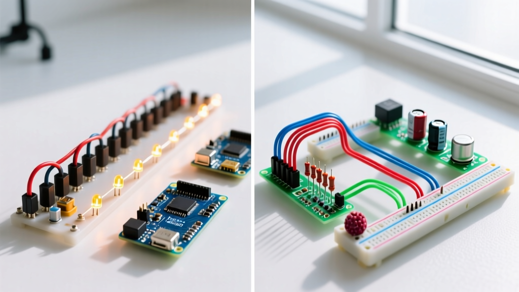

If you need independent operation, constant voltage delivery, and fault tolerance, parallel is the undisputed winner for home wiring, solar arrays, and battery banks. If you need to step up voltage, divide voltage across components, or limit current with minimal wiring, series is the correct choice for LED strings, high-voltage DC transmission, and simple current-limiting networks. There is no universal 'better' topology; the right choice depends entirely on whether your design priority is voltage manipulation or load independence.
The Single Physical Difference That Drives Everything
Every mathematical and behavioral difference between these two topologies stems from one physical reality: the path available for current flow.
In a series circuit, there is exactly one continuous path for electrons to travel from the negative terminal to the positive terminal. Because the current has nowhere else to go, the amperage is identical through every component, but the voltage drops (divides) across each resistance. Think of it like a single-loop water pipe with multiple water wheels; the same volume of water flows through each wheel, but the water pressure drops after each one.
In a parallel circuit, the current path splits into multiple branches. Because each branch connects directly across the same two nodes, the voltage is identical across every branch, but the current divides based on each branch's resistance. This single physical difference dictates how Kirchhoff’s Voltage Law (KVL) and Kirchhoff’s Current Law (KCL) apply to your design.
| Parameter | Series Topology | Parallel Topology |
|---|---|---|
| Voltage (V) | Divides: V_total = V1 + V2 + V3... | Constant: V_total = V1 = V2 = V3... |
| Current (I) | Constant: I_total = I1 = I2 = I3... | Divides: I_total = I1 + I2 + I3... |
| Resistance (R) | Adds: R_total = R1 + R2 + R3... | Decreases: 1/R_total = 1/R1 + 1/R2... |
| Power (P) | P_total = P1 + P2 (lowest R dissipates most) | P_total = P1 + P2 (lowest R dissipates most) |
| Failure Mode (Open) | Kills the entire circuit (current path broken) | Only the failed branch goes dark; others run |
| Failure Mode (Short) | Current increases; remaining components see higher voltage | Massive current spike; trips main breaker/fuse |
Head-to-Head Comparison: Series vs Parallel
When moving from textbook theory to actual bench or jobsite wiring, the mathematical rules translate into practical trade-offs regarding copper costs, protection devices, and maintenance.
| Criteria | Series Circuits | Parallel Circuits |
|---|---|---|
| Load Independence | Poor. Adding/removing a load changes current for all. | Excellent. Each load operates independently at source voltage. |
| Fault Tolerance | Low. A single blown bulb or open wire kills the whole string. | High. A fault in one branch leaves the rest of the system live. |
| Protection Cost | Low. One main fuse/breaker protects the single path. | High. Requires individual branch breakers or fuses for safety. |
| Wire Gauge Requirements | Uniform. Wire only needs to handle the single string current. | Variable. Main feeder must be massive; branch wires can be smaller. |
| Voltage Drop Impact | Intentional. Used to drop voltage across specific components. | Parasitic. Must be minimized to ensure equal voltage at all loads. |
Where They Are Strictly Not Interchangeable
While you can theoretically wire almost anything in either configuration, physics and electrical codes make certain topologies mandatory for specific applications.
Lithium Battery Banks: You cannot wire raw lithium-ion or LiFePO4 cells in parallel without first matching their voltages to within 0.05V. If you parallel a 3.2V cell with a 3.6V cell, the higher-voltage cell will dump massive, unregulated current into the lower-voltage cell, leading to thermal runaway and fire. Conversely, wiring them in series requires a Battery Management System (BMS) to balance the cells; otherwise, the weakest cell will be over-discharged or overcharged during cycling.
The Decision Framework: Choose A When / Choose B When
Use this framework to select your topology based on your project's primary constraints.
Choose Series When:
- You need to step up voltage: Wiring four 12V solar panels in series yields 48V nominal, allowing you to use thinner, cheaper wire (like 10 AWG THHN) to run a long distance to an MPPT charge controller without severe voltage drop.
- You are designing simple LED strings: A series string of LEDs with a single current-limiting resistor ensures identical brightness across all diodes, provided the supply voltage exceeds the combined forward voltage drops.
- Cost and copper are the primary constraints: Series wiring requires significantly less copper and fewer overcurrent protection devices, making it cheaper for simple, low-complexity loads like holiday light strings or basic heating elements.
Choose Parallel When:
- You need constant voltage across all loads: Home appliances, 12V DC automotive accessories, and server rack power supplies all require a stable 120V, 12V, or 48V nominal supply regardless of what else is turned on.
- You are scaling battery capacity (Amp-hours): Wiring four 12V 100Ah batteries in parallel keeps the system at 12V but increases capacity to 400Ah, ideal for high-current, low-voltage applications like winches or RV inverters.
- Fault tolerance is critical: In marine DC panels or critical server infrastructure, parallel branching ensures that a short circuit in the navigation lights doesn't kill power to the bilge pump or the communication radios.
Real-World Edge Cases in 48V DC Systems
The most common point of confusion for DIY solar and off-grid builders is configuring a 48V LiFePO4 battery bank using four 12V 100Ah modules. You have two choices: a 4S (4 in series) configuration or a 4P (4 in parallel) configuration with a 48V native battery.
In a 4S (Series) setup, you connect positive to negative down the line. The voltage stacks to 51.2V nominal, but the capacity remains 100Ah. The physical advantage here is that the current flowing through the main busbars is relatively low (e.g., a 3000W inverter pulls about 60A). You can safely use 2/0 AWG copper cable. However, if one internal BMS faults and opens, the entire 48V system goes dead instantly.
In a 4P (Parallel) setup using native 48V 100Ah batteries, you connect positive to positive and negative to negative. The voltage stays at 51.2V, but capacity scales to 400Ah. The edge case here is circular currents. If the interconnecting cables are not cut to the exact same length and resistance, the batteries will not share loads equally. The battery with the lowest cable resistance will do the heavy lifting, age faster, and potentially trip its BMS. To fix this, you must wire them using a diagonal busbar topology or perfectly matched cable lengths.
Ultimately, the choice between electrical series vs parallel isn't about which is superior; it's about manipulating voltage and current to match the physical and economic constraints of your specific build. For a deep dive into calculating the exact voltage drop for your chosen topology, refer to the series and parallel circuit fundamentals on All About Circuits to verify your math before cutting wire.


