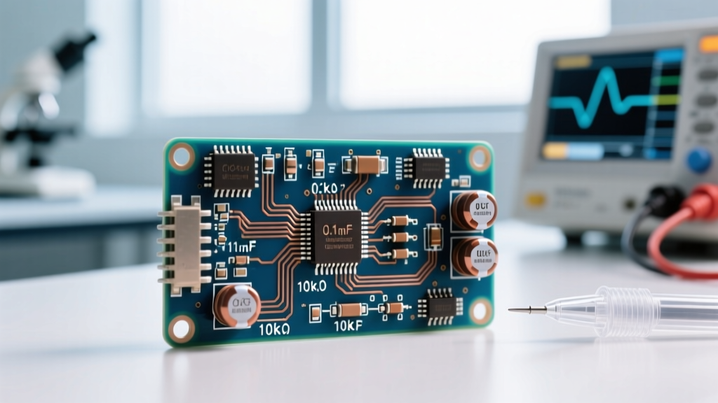

An ECG high pass filter cutoff frequency is the specific -3dB threshold (typically 0.05 Hz or 0.5 Hz) below which low-frequency baseline wander is attenuated while the cardiac waveform passes unaltered. Setting this frequency dictates exactly how much low-frequency phase distortion and baseline drift rejection occurs in your front-end analog signal chain. Beginners frequently confuse the high-pass filter with the low-pass filter (which cuts high-frequency EMG/muscle noise) or the 50/60 Hz notch filter (which kills mains hum), but the HPF is solely responsible for taming respiration artifacts, electrode half-cell potential drift, and patient motion baseline shifts.
The Math Behind the ECG High Pass Filter Cutoff Frequency
To build a first-order active or passive RC high-pass filter, the governing equation is straightforward:
fc = 1 / (2πRC)
Because the target frequencies are sub-Hertz, you are forced to use large resistor or capacitor values. Let's walk through a real bench calculation for a diagnostic-grade ECG front-end targeting a 0.05 Hz cutoff.
Target fc = 0.05 Hz. We select a standard capacitor value of C = 3.3 µF.
Solving for R: R = 1 / (2 × π × 0.05 × 3.3 × 10-6) = 964,369 Ω.
The nearest standard 1% E96 series resistor is 976 kΩ.
Recalculating with 976 kΩ yields an actual cutoff of 0.0494 Hz — well within clinical tolerance.
However, the math is only half the battle. At 0.05 Hz, a 3.3 µF capacitor presents an impedance of nearly 1 MΩ. If you place this passive RC network directly at the input of your instrumentation amplifier, the amplifier's input bias current flowing through that 976 kΩ resistor will generate a massive DC offset voltage. For example, an older LM324 op-amp with a 20 nA bias current would generate a 19.5 mV offset. If your front-end gain is set to 100, that offset becomes 1.95V, instantly saturating a 3.3V ADC.
The fix: Always use a CMOS or chopper-stabilized instrumentation amplifier with picoamp-level bias currents (like the TI INA333 at 10 pA typical), or place this high-pass filter after the initial unity-gain buffering stage.
Where You Meet This in Practice
In clinical and hobbyist ECG design, you will encounter two distinct cutoff standards mandated by the American Heart Association (AHA) and the American College of Cardiology. Understanding the difference prevents you from designing a monitor that accidentally masks a heart attack.
Monitoring Mode (0.5 Hz): Used for continuous telemetry, wearables, and Holter monitors. The higher cutoff aggressively rejects baseline wander caused by patient movement and respiration, at the accepted cost of mild ST-segment distortion.
According to the canonical AHA Scientific Statement on ECG Standardization, the 0.05 Hz threshold is non-negotiable for diagnostic accuracy. If you are building a wearable device for a running athlete, however, 0.05 Hz will result in an unreadable, wildly swinging baseline due to motion artifact. You must design for the specific use case.
Decision Tree: Picking Your Cutoff and Components
Use this decision matrix to lock in your analog front-end parameters. Do not attempt to compromise between these two modes; pick the one that matches your end application.
| Application Scenario | Target Cutoff | Recommended R | Recommended C | Concrete BOM Pick |
|---|---|---|---|---|
| Clinical 12-lead, resting bench ECG, ST-segment analysis | 0.05 Hz | 976 kΩ (0.1%) | 3.3 µF | Default Pick: Vishay thin-film 976k + WIMA polypropylene 3.3µF |
| Wearable, Holter, fitness tracker, high-motion telemetry | 0.5 Hz | 97.6 kΩ (1%) | 3.3 µF | Default Pick: Yageo 97.6k + Murata C0G 3.3µF |
Final Verdict: If you are building a general-purpose bench ECG for hobbyist diagnostics or a university lab, lock in 0.05 Hz with a 976 kΩ thin-film resistor and a 3.3 µF C0G/film capacitor. This gives you the most faithful waveform reproduction and prevents false ST-elevation readings.
The Dielectric Trap: Why Your Capacitor Choice Matters
Here is where most open-source ECG projects fail on the bench. The math tells you to use a 3.3 µF capacitor, so a hobbyist grabs a standard 0805 X7R MLCC (Multi-Layer Ceramic Capacitor) from their parts bin. The circuit simulates perfectly, but on the bench, every time the patient breathes or the PCB flexes, massive spikes appear in the ECG trace.
This is caused by the piezoelectric effect and dielectric absorption inherent in Class II ceramics (X7R, X5R, Y5V). Barium titanate dielectrics generate spurious voltages when subjected to mechanical stress (microphonics) or thermal gradients. In a high-impedance, sub-Hertz filter, these microphonic voltages are indistinguishable from premature ventricular contractions (PVCs) or T-wave alternans.
Furthermore, standard 5% carbon film resistors generate excess thermal and current noise at these high impedances. Always specify 0.1% thin-film resistors for the RC timing network to keep the noise floor below the 10 µV resolution required for pediatric ECGs.
FAQ: ECG Filter Design Questions
Q: Can I just skip the analog high-pass filter and do it in software after the ADC?
A: No. While you can apply a digital high-pass filter in an MCU or DSP, baseline wander from electrode half-cell potentials can easily exceed ±300 mV. If you do not strip this out in the analog domain with an RC high-pass filter, the wander will consume your entire ADC dynamic range or saturate your programmable gain amplifier (PGA) before the digital filter ever sees it. You need analog AC coupling to keep the signal centered in your ADC window.
Q: What do people commonly confuse the high-pass filter with?
A: Designers often conflate the HPF with the low-pass filter (which typically cuts off at 40 Hz or 150 Hz to remove skeletal muscle EMG noise) or the notch filter (which targets exactly 50 Hz or 60 Hz to remove AC mains interference). The HPF only deals with sub-Hertz baseline drift.
Q: Does a higher cutoff frequency like 1.0 Hz improve motion artifact rejection?
A: It rejects more motion artifact, but it severely distorts the QRS complex and ST-segment. Research published in studies on ECG signal filtering demonstrates that pushing the high-pass cutoff above 0.5 Hz introduces unacceptable phase distortion for any clinical or diagnostic interpretation. Stick to the 0.5 Hz ceiling for monitoring.
Q: My 0.05 Hz filter takes too long to settle after a lead disconnect. How do I fix this?
A: A 0.05 Hz RC filter has a time constant (τ = RC) of roughly 3.2 seconds, meaning it takes over 15 seconds to settle to 99% after a massive DC step like a lead plugging in. Implement a "fast restore" or "baseline wander cancellation" circuit using an analog switch to temporarily short the capacitor or drop the resistor value during lead attachment, then switch back to the 0.05 Hz components for normal operation.


