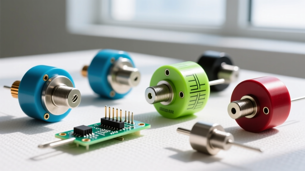
A DC drive is an electronic controller that regulates the speed, torque, and direction of a direct current motor by precisely varying the armature voltage and field current. In a real installation, it transforms a brutal, high-inrush, fixed-speed motor into a smoothly accelerating, dynamically braked, and precisely regulated mechanical output. Hobbyists and junior technicians commonly confuse industrial DC drives with simple open-loop PWM motor controllers or AC Variable Frequency Drives (VFDs), missing the critical closed-loop tachometer feedback and independent field excitation that define a true industrial DC drive system.
How DC Drives Actually Control Speed (The Theory)
To understand a DC drive, you have to look at the fundamental DC motor speed equation: N = (V - IaRa) / kΦ. Speed (N) is directly proportional to the armature voltage (V) minus the internal voltage drop, and inversely proportional to the magnetic field flux (Φ). A modern industrial DC drive manipulates these variables in two distinct operating zones.
Zone 1: Below Base Speed (Armature Voltage Control)
From zero up to the motor's nameplate base speed, the drive holds the field current at its maximum rated value (constant flux). It then ramps up the armature voltage from 0V to the rated voltage (e.g., 500V DC). This gives you constant torque and variable speed. Think of armature voltage like the water pressure pushing through a pipe, while the magnetic field flux is the physical diameter of the pipe; maximizing the pipe diameter and increasing the pressure gives you maximum pushing force.
Zone 2: Above Base Speed (Field Weakening)
Once the armature hits its maximum rated voltage, the drive can't push it any faster without risking insulation breakdown. To go faster, the drive intentionally reduces the field current (weakens the flux, Φ). Because flux is in the denominator of our speed equation, reducing it forces the motor to spin faster to generate enough Back-EMF to balance the armature voltage. This gives you constant power but dropping torque.
Worked Numeric Example: Sizing and Speed Calculation
Let's size a drive and calculate the internal voltage drops for a standard industrial setup.
- Motor Nameplate: 10 HP, 500V DC Armature, 17.5A Armature Full Load Amps (FLA), 300V/1.2A Field, 1750 RPM base speed.
- Armature Resistance (Ra): 1.2 Ω (measured cold, adjusted for operating temp).
Step 1: Sizing the Drive
According to NEMA MG 1 standards and NEC Article 430.22 for continuous duty, we must size the drive for 125% of the motor's FLA.
Calculation: 17.5A × 1.25 = 21.87A.
Selection: We select a 25A or 30A rated DC drive (such as an ABB DCS800 or Sprint Electric 590P series) to handle the continuous thermal load.
Step 2: Calculating Back-EMF at Full Load
When the motor is running at 1750 RPM drawing full 17.5A, what is the actual Back-EMF (E) spinning the rotor?
Formula: E = V - (Ia × Ra)
Calculation: E = 500V - (17.5A × 1.2 Ω) = 500V - 21V = 479V.
The drive must supply 500V to the terminals, but 21V of that is just wasted heat pushing current through the copper windings. Only 479V is actually doing mechanical work.
Where You Meet DC Drives in Practice
While AC VFDs have taken over general-purpose pumping and fan applications, DC drives remain dominant in specific, high-demand niches in 2026 due to their superior low-speed torque and simple regenerative braking capabilities.
- Web Tensioning (Paper, Steel, and Film Mills): As a roll of paper unwinds, its diameter shrinks. The DC drive must constantly adjust torque and speed to keep the tension perfectly uniform, preventing the web from snapping. The linear torque-to-current relationship of a DC motor makes this mathematically trivial compared to AC vector control.
- Hoists and Cranes: Lowering a multi-ton load requires regenerative braking. A DC drive can seamlessly push the generated armature voltage back into the AC line via its fully controlled thyristor bridge, holding the load securely without burning up mechanical brake pads.
- Extruders and Mixers: These applications require massive starting torque at near-zero RPM to break cold, viscous materials loose. A DC drive delivers 150% to 200% locked-rotor torque effortlessly.
Real-World Scenario: The Extruder Speed Droop Disaster
Theory is clean; the jobsite is not. Here is a classic troubleshooting scenario that highlights why tuning a DC drive is an art form.
The Setup:
A plastic recycling plant uses a 15 HP, 460V DC motor to drive an extruder screw. The drive is an older analog-regenerated unit recently retrofitted with a digital control board. The operator commands a steady 600 RPM.
The Numbers:
Running empty (unloaded), the motor draws 6A and holds exactly 600 RPM. When the hopper is flooded with cold plastic pellets, the load spikes and the armature current jumps to 38A. The armature circuit resistance (including brushes, interpoles, and cabling) is 0.85 Ω.
The Outcome:
The moment the plastic hits the screw, the motor speed droops violently from 600 RPM down to 510 RPM. The extruder barrel overheats, the plastic burns, and the line shuts down.
What Went Wrong:
The digital board's IR Compensation was disabled. Because the drive was running in open-loop voltage mode (no tachometer feedback), it simply outputted a fixed voltage to achieve 600 RPM unloaded. But under load, the voltage drop across the armature resistance increased massively: 38A × 0.85 Ω = 32.3V. The drive failed to add this 32.3V back into the supply to compensate for the internal drop, effectively starving the motor of the Back-EMF it needed to maintain speed. The fix: Enable IR compensation in the drive parameters and calibrate it to the measured 0.85 Ω circuit resistance, or wire up a physical tachometer for closed-loop feedback.
DC Drives vs. PWM Controllers vs. AC VFDs
Choosing the right controller depends entirely on the mechanical demands of the load. Here is how they stack up against each other on the workbench.
| Feature | Industrial DC Drive | AC VFD (Vector Control) | Hobby DC PWM Controller |
|---|---|---|---|
| Speed Control Method | Armature Voltage & Field Current | PWM Frequency & Voltage (V/Hz or FOC) | Simple Duty Cycle Chopping |
| Zero-Speed Torque | 150% - 200% (Continuous) | 150% (Requires Flux Vector & Encoder) | Poor (Motor stalls and overheats) |
| Regenerative Braking | Native (Line-regenerative bridges) | Requires expensive Active Front End (AFE) | None (Requires braking resistor) |
| Feedback Required | Optional (Tach/Encoder for precision) | Optional (Sensorless or Encoded) | None (Open loop only) |
| Typical 2026 Cost (10HP) | $1,800 - $2,500 | $600 - $1,200 | $40 - $90 |
Frequently Asked Questions
Can I use an AC VFD to run a DC motor?
No. An AC VFD outputs a high-frequency, pulse-width-modulated AC waveform designed to create a rotating magnetic field in an AC stator. Feeding this into a DC armature will result in massive eddy current losses, severe overheating, and likely a catastrophic insulation failure. You must use a dedicated DC drive that outputs rectified, smoothed DC voltage.
Why do DC drives use thyristors (SCRs) instead of modern IGBTs?
While modern ABB and Sprint Electric drives are incorporating IGBT choppers for the armature output to reduce ripple, the input line-rectifier still heavily relies on phase-controlled thyristors (SCRs). SCRs are incredibly robust, handle massive surge currents during motor starts, and naturally allow for line-regeneration (pushing power back to the grid) simply by shifting the firing angle past 90 degrees.
What is the difference between a 1-quadrant and a 4-quadrant DC drive?
A 1-quadrant (non-regenerative) drive can only spin the motor forward and drive torque forward. It uses a simple diode bridge for the AC input. A 4-quadrant (regenerative) drive uses two fully controlled thyristor bridges in anti-parallel. This allows it to drive forward, brake forward, drive reverse, and brake reverse—making it mandatory for hoists, elevators, and dynamometer test stands.