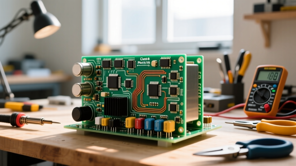
A logic gate is a physical electronic circuit that performs a boolean logical operation on one or more binary voltage inputs to produce a single binary voltage output. In a real circuit, it changes continuous, noisy analog voltages into clean, discrete digital states (HIGH or LOW), acting as the fundamental building block for memory and decision-making. Beginners commonly confuse the abstract boolean symbol (the math) with the physical implementation (the transistor switching thresholds and propagation delays), or assume 'building' a gate means wiring up a pre-packaged 74HC00 IC rather than constructing the underlying transistor network from scratch.
Discrete Logic Families: RTL, DTL, TTL, and CMOS
To understand how to build a logic gate, you must first understand the evolution of transistor-level logic. Before integrated circuits packaged thousands of gates into a single silicon die, engineers built logic using discrete Resistors, Diodes, and Transistors. Each family makes a different trade-off between speed, power consumption, and noise immunity. The table below outlines the real-world specifications of the four primary discrete and early-IC logic families.
| Logic Family | Typical Vcc | Propagation Delay | Power per Gate | Standard Fan-out |
|---|---|---|---|---|
| RTL (Resistor-Transistor) | 3V - 5V | ~500 ns | 5 mW | 3 |
| DTL (Diode-Transistor) | 5V | ~25 ns | 10 mW | 8 |
| TTL (74LS Series) | 5V ±5% | ~9 ns | 2 mW | 10 |
| CMOS (74HC Series) | 2V - 6V | ~15 ns | 0.01 mW (static) | 20+ |
While CMOS dominates modern microcontrollers, RTL remains the most accessible family for learning how to build a logic gate on a breadboard because it requires only standard NPN transistors and carbon film resistors. For a deep dive into the historical transition between these families, the All About Circuits digital logic textbook provides excellent schematic breakdowns.
Step-by-Step: Building a 2-Input RTL NOR Gate
Let's build a 2-input NOR gate using Resistor-Transistor Logic (RTL). In an RTL NOR gate, two NPN transistors are placed in parallel. Their emitters share a common ground, and their collectors are tied together and pulled up to Vcc via a single resistor. If Input A OR Input B goes HIGH, the corresponding transistor turns on, pulling the shared output node LOW.
1. Calculate the Collector Pull-up Resistor (Rc)
When a transistor turns on, it enters saturation. According to the ON Semi 2N3904 datasheet, the collector-emitter saturation voltage (Vce_sat) is approximately 0.2V at low currents. We want a collector current (Ic) of 2mA to keep power low while still driving a high-impedance load.
- Rc = (Vcc - Vce_sat) / Ic
- Rc = (5V - 0.2V) / 0.002A = 2,400 Ω
Decision: Use a standard 2.2 kΩ resistor for Rc. This yields a slightly higher Ic of ~2.18mA, which is perfectly safe.
2. Calculate the Base Input Resistors (Rb)
To ensure the transistor acts as a hard switch (saturation) rather than a linear amplifier, we must overdrive the base. The 2N3904 has a minimum DC current gain (hFE) of 100, but in switching applications, we use a 'forced beta' of 10 to 20 to guarantee saturation across temperature variations.
- Required Base Current (Ib) = Ic / Forced_Beta = 2.18mA / 20 = 0.109 mA (109 μA)
- Assuming a HIGH input of 5V and a base-emitter voltage drop (Vbe_sat) of 0.7V:
- Rb = (Vin_high - Vbe_sat) / Ib
- Rb = (5V - 0.7V) / 0.000109A = 39,449 Ω
Decision: Use a standard 33 kΩ or 39 kΩ resistor for the base inputs. A 33 kΩ resistor provides ~130 μA of base current, ensuring a rock-solid LOW output when triggered.
Where You Meet Discrete Logic in Practice
You might wonder why you need to know how to build a logic gate from discrete components when a 74HC32 quad-OR gate costs $0.50. You meet discrete logic topology constantly in modern embedded systems and industrial controls, usually disguised as 'interfacing' or 'buffering'.
- ESP32 to 12V Relay Interfacing: When you use an ESP32 GPIO (3.3V logic) to drive a 12V Songle relay coil, you are building a discrete logic inverter/buffer. The GPIO pin acts as the input, the base resistor limits current, and the NPN transistor switches the 12V load. If you don't calculate the base resistor correctly using the RTL principles above, the transistor operates in the linear region, overheats, and burns out.
- Industrial Hardware Interlocks: In high-noise environments (like motor drives), microcontrollers can brownout or experience watchdog resets. Safety-critical interlocks (e.g., 'If Door A is open AND E-Stop is pressed, kill the contactor') are often built using discrete DTL or RTL gates on the PCB so the logic state survives a total MCU crash.
- Signal Level Shifting: Open-collector RTL topologies are the exact same physics used in I2C pull-up networks and open-drain level shifters translating 5V sensor outputs down to 3.3V Raspberry Pi Pico inputs.
Debugging and Common Mistakes
When your breadboard logic gate fails to output the correct truth table, the issue is almost always analog, not digital. Here is how to troubleshoot discrete gates with a multimeter.
Symptom: Output is stuck at 2.5V instead of pulling down to 0.2V (LOW).
Cause: The transistor is in the linear (active) region, not saturation. Your base resistor (Rb) is too large, or your input voltage is sagging below the logic HIGH threshold.
Fix: Measure Vbe with your multimeter. If it reads 0.6V, the transistor is barely turning on. Drop your Rb value by one standard step (e.g., swap 47kΩ for 33kΩ) to increase base drive.
Symptom: Output is floating or randomly toggling when inputs are disconnected.
Cause: Floating inputs. Unlike CMOS gates which have internal protection networks that can cause massive current draw on floating pins, RTL bases act like antennas picking up 60Hz mains hum.
Fix: Always tie unused discrete logic inputs to GND via a 10kΩ pull-down resistor. Never leave an NPN base floating.
Frequently Asked Questions
Can I build an AND gate using RTL?
Standard RTL naturally creates NOR and NAND (with modified topology) gates. Building an AND gate directly in RTL is inefficient; it is better to build an RTL NOR gate followed by an RTL inverter (NOT gate), or switch to Diode-Transistor Logic (DTL) where diodes handle the AND function natively.
What is the maximum switching speed of a discrete 2N3904 logic gate?
While the 2N3904 has a transition frequency (fT) of 300 MHz, the parasitic capacitance of the breadboard and the Miller effect in the saturated transistor limit practical RTL gate switching to roughly 1 MHz to 2 MHz before propagation delay and signal degradation ruin the logic levels.