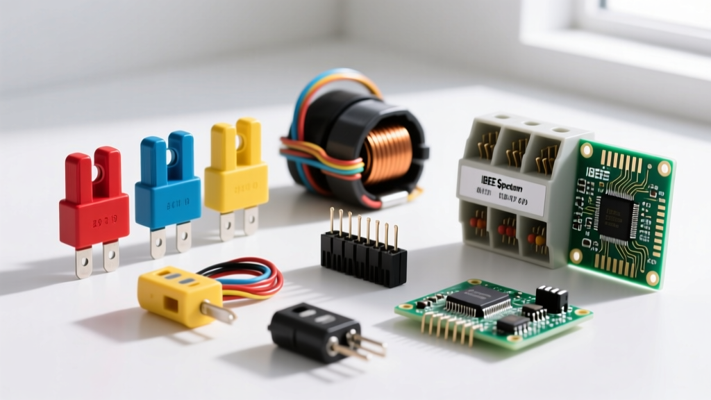

If you are wiring auxiliary lights, a winch, or a custom fuel pump, you need to know exactly which fuse to grab. Auto fuse colors follow the SAE J554 and ISO 8820 standards, providing a universal visual code for amperage. The direct answer for standard blade fuses is: Violet (3A), Pink (4A), Orange (5A), Brown (7.5A), Red (10A), Blue (15A), Yellow (20A), Clear/White (25A), and Green (30A).
However, matching the color to the wire gauge is only half the job. When protecting electromechanical components like automotive relays or contactors, you must size the fuse based on the specific side of the relay you are protecting—the low-current coil side or the high-current contact side—and account for the load's inrush characteristics. Here is the bench-tested guide to selecting, wiring, and testing auto fuses in electromechanical circuits.
The Standard Auto Fuse Color and Rating Chart
Automotive blade fuses come in several physical sizes (Micro2, Low-Profile Mini, Mini, ATO/ATC, and Maxi), but the color-to-amperage mapping remains consistent across all of them. Below is the data-dense reference chart for standard automotive blade fuses.
| Color | Amp Rating | Standard Type | Interrupting Capacity (AIC) at 14V DC | Max Wire Gauge (Copper) |
|---|---|---|---|---|
| Violet | 3A | Mini / ATO | 1,000A | 18 AWG |
| Pink | 4A | Mini / ATO | 1,000A | 18 AWG |
| Orange | 5A | Mini / ATO | 1,000A | 16 AWG |
| Brown | 7.5A | Mini / ATO | 1,000A | 16 AWG |
| Red | 10A | Mini / ATO / Maxi | 1,000A | 14 AWG |
| Blue | 15A | Mini / ATO / Maxi | 1,000A | 14 AWG |
| Yellow | 20A | ATO / Maxi | 1,000A | 12 AWG |
| Clear / White | 25A | ATO / Maxi | 1,000A | 10 AWG |
| Green | 30A | ATO / Maxi | 1,000A | 10 AWG |
Which Rating Column Governs This Load?
When selecting a fuse, beginners often look only at the Amp Rating, but the Interrupting Capacity (AIC) is equally critical. The Amp Rating dictates the steady-state current the fuse will carry indefinitely without opening. The Interrupting Capacity (typically 1,000A for standard 14V DC auto fuses) dictates the maximum fault current the fuse can safely clear without shattering or sustaining an arc. If you install a standard 1,000A AIC blade fuse on a 48V DC solar or EV battery bus where short-circuit currents can exceed 5,000A, the fuse body will violently rupture. Always ensure the fuse AIC exceeds the available fault current of the power source.
Sizing Fuses for Electromechanical Loads: Coil vs. Contact Side
Automotive relays (like the ubiquitous Bosch-style 5-pin relay) isolate a low-current control circuit from a high-current load circuit. You must fuse both sides, but the sizing methodology is entirely different.
| Parameter | Coil Side (Control - Pins 85/86) | Contact Side (Load - Pins 30/87) |
|---|---|---|
| Voltage Rating | 12V DC (9V-16V operable) | 14V DC Nominal (up to 28V) |
| Current Rating | ~150 mA (Coil draw) | 30A / 40A (Resistive load limit) |
| Breaking Capacity | N/A (Switch/ECU handles this) | 1,000A (Fault clearing via fuse) |
| Fuse Sizing Rule | Protect the driving wire/switch (e.g., 2A or 3A) | Protect the load wire based on inrush (e.g., 15A to 40A) |
Coil Side Wiring and Flyback Protection
The coil side of a relay is an inductor. When you wire the coil side (pins 85 and 86) to a DC source, you are creating an electromagnet. When the control switch opens, the collapsing magnetic field generates a massive reverse-voltage spike (inductive kickback) that can easily exceed 100V, instantly frying the driving transistor in an ECU or pitting the contacts of a mechanical toggle switch.
Selection Decision Path by Load Type
On the contact side (pins 30 and 87), the fuse must be sized to protect the wire while surviving the load's startup surge. Use this decision tree to select the correct auto fuse color and type:
| Load Type | Inrush Characteristic | Fuse Selection Rule | Real-World Example |
|---|---|---|---|
| Resistive | 1.0x (No inrush spike) | 100% of steady-state current. Fast-blow is fine. | Heated seats, halogen lighting, rear window defroster. |
| Inductive | 5x to 10x spike for milliseconds | Slow-blow (Time-delay) or size at 150% of FLA. | Solenoids, fuel pumps, power windows. |
| Motor | 10x to 15x spike during stall/start | Slow-blow, sized to Full Load Current (FLC) + 25%. | Radiator fans, winches, blower motors. |
For deeper technical specifications on automotive blade fuse interrupting ratings and physical dimensions, refer to the Littelfuse Automotive Fuses catalog and the SAE J554 standard documentation.
Testing, Curves, and Replacement Rules
Knowing how to properly test a fuse and understanding when to replace versus repair the circuit separates professional installers from amateurs who chase electrical gremlins for days.
How to Test Auto Fuses: Dead and Live
Dead Testing (Continuity): Remove the fuse from the panel. Set your multimeter to the continuity or resistance (Ω) setting. Place one probe on each of the exposed metal blades. A good fuse will read less than 1 ohm and beep. A blown fuse will read 'OL' (Open Loop) or infinite resistance. Visually inspecting the element through the plastic window is notoriously unreliable, especially in bright sunlight or with Micro2 fuses; always verify with a meter.
Live Testing (Voltage Drop): Leave the fuse seated in the energized panel. Set your multimeter to DC Voltage. Blade fuses have two small exposed test tabs on the top face. Place your black probe on a known good chassis ground, and touch the red probe to one test tab, then the other.
• If you read 12V-14V on both tabs, the fuse is good.
• If you read 12V-14V on one tab and 0V on the other, the fuse is blown (the open element is dropping all the system voltage).
• If you read 0V on both tabs, the fuse is fine, but there is no power reaching the panel (check the main feeder or upstream fusible link).
Fuses vs. Breakers: The Curve Discussion
A common mistake in automotive and marine wiring is treating fuses and thermal circuit breakers as interchangeable. They are not. An automotive blade fuse has a specific time-current curve. A 20A fast-acting blade fuse will clear a 100A short circuit in milliseconds, limiting the let-through current (I²t) to a safe level that prevents the wire insulation from melting.
Conversely, a 20A auto-reset thermal breaker (Type 1) relies on a bimetallic strip that heats up and bends. Its trip curve is vastly slower. If you replace a 20A blade fuse with a 20A thermal breaker on a circuit with thin 16 AWG wire, a dead short will cause the wire to glow red-hot and melt the insulation long before the breaker's thermal mass reacts. Only use thermal breakers on heavy-gauge feeder circuits (like a winch or starter motor) where high, sustained inrush currents would otherwise nuisance-blow a standard fuse, and always ensure the wire ampacity exceeds the breaker rating by a safe margin.
When to Repair vs. Replace
Never repair a fuse. Wrapping foil around a blown element or jamming a paperclip into the fuse slot bypasses the engineered I²t let-through limits and is a primary cause of vehicle electrical fires. If a fuse blows once, replace it with the exact same amperage and physical size (e.g., do not force a standard ATO into a Mini slot using adapters, as this alters the thermal dissipation profile). If the replacement fuse blows immediately or shortly after installation, stop replacing fuses and repair the circuit. A repeatedly blowing fuse indicates a hard fault: a chafed wire shorting to the chassis, a seized motor drawing stall current, or a failed flyback diode allowing voltage spikes to arc across the relay contacts. Find the fault with a wiring diagram and a multimeter before energizing the circuit again.


