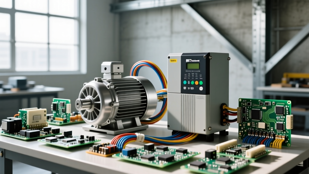
An AC drive (often called a Variable Frequency Drive or VFD) is an electronic controller that varies the speed and torque of an AC motor by adjusting the frequency and voltage of the power supplied to it. Instead of slamming a motor with fixed 60Hz line voltage and relying on mechanical throttling, an AC drive changes the actual electrical waveform entering the circuit, converting fixed-frequency mains power into a synthesized, variable-frequency output. This allows you to precisely dictate motor speed, achieve soft starting, and reclaim massive amounts of energy in variable-torque applications like pumps and fans.
The Core Mechanism: Rectify, Filter, Invert
To understand what an AC drive does to your circuit, you have to look inside the chassis. The power flows through three distinct stages:
- Rectifier (AC to DC): A diode bridge converts the incoming 3-phase AC mains into pulsating DC.
- DC Bus (Filter): A bank of large electrolytic capacitors smooths the pulsating DC into a clean, high-voltage DC bus. For a 480V AC input, this DC bus sits at roughly 680V DC.
- Inverter (DC to Simulated AC): Insulated Gate Bipolar Transistors (IGBTs) switch the DC bus on and off at high frequencies (typically 2 kHz to 15 kHz). By varying the width of these pulses (Pulse Width Modulation, or PWM), the drive simulates a lower-frequency, lower-voltage AC sine wave to the motor.
Worked Numeric Example: The 4-Pole Motor at Half Speed
Let’s put numbers to the theory. You have a standard 10 HP, 4-pole, 460V, 60Hz 3-phase induction motor. You want to run it at exactly half speed using an AC drive.
Step 1: Calculate Base Synchronous Speed
The formula for synchronous speed is Ns = (120 × f) / P, where f is frequency and P is the number of poles.
Ns = (120 × 60) / 4 = 1800 RPM. (Actual full-load speed will be around 1750 RPM due to slip).
Step 2: Calculate Target Frequency for Half Speed
To get 900 RPM, you need to halve the frequency:
f = (900 × 4) / 120 = 30 Hz.
Step 3: Calculate Required Output Voltage
First, find the motor's rated V/Hz ratio: 460V / 60Hz = 7.67 V/Hz.
To maintain this magnetic flux at 30 Hz, the drive must output:
30 Hz × 7.67 V/Hz = 230 Volts.
The AC drive synthesizes a 230V, 30Hz output using its 680V DC bus by adjusting the PWM duty cycle. The motor runs smoothly at half speed, drawing roughly half the current and consuming about one-eighth the power (since fan/pump power scales with the cube of speed).
Where You Meet This in Practice (And What It Isn't)
You will encounter AC drives in almost every modern industrial or commercial setting: HVAC blower motors, municipal water pump stations, CNC machine spindles, and warehouse conveyor belts. According to the US Department of Energy, adding VFDs to centrifugal pumps and fans can reduce energy consumption by 20% to 50% compared to mechanical throttling valves.
What people commonly confuse it with: The Soft Starter.
A soft starter is a completely different device. It uses SCRs (Silicon Controlled Rectifiers) to chop the voltage waveform, reducing the starting torque and inrush current during the first 5 to 10 seconds of startup. Once the motor reaches full speed, the soft starter bypasses itself, and the motor runs directly across the fixed 60Hz line. A soft starter cannot control running speed; an AC drive stays in the circuit and controls speed continuously.
Real-World Scenario Walkthrough: The Reflected Wave Motor Killer
Theory is clean; the jobsite is not. Here is a scenario that destroys equipment when installers treat an AC drive like a simple contactor.
The Setup: A woodshop installs a 10HP, 480V dust collector. The Yaskawa GA800 AC drive is mounted in a clean electrical room, but the motor is 150 feet away. The installer runs standard 8 AWG THHN wire in PVC conduit to save money, rather than using shielded VFD cable. They use a standard off-the-shelf induction motor.
The Numbers: The drive's IGBTs switch the 680V DC bus at 4 kHz. The rise time (dV/dt) of these pulses is incredibly fast—often switching 680 volts in less than 0.1 microseconds. Because the 150-foot cable has parasitic capacitance and inductance, it acts as a transmission line. The impedance mismatch between the cable and the motor windings causes the fast-rising voltage pulses to reflect back from the motor terminals.
The Outcome: After three weeks of operation, the motor smells like ozone and the drive trips on a ground fault. The motor is dead.
What Went Wrong: The reflected waves叠加 (superimposed) on the incoming pulses, creating voltage spikes at the motor terminals that reached nearly 1,300V peak—far exceeding the 1,000V limit of standard Class F motor insulation. The first few turns of the motor windings shorted out. To fix this, the shop should have specified an inverter-duty motor (built to NEMA MG1 Part 31 standards with reinforced spike-resistant enamel) and installed an output dV/dt filter at the drive to slow the voltage rise time.
Specifying the Right Hardware: Avoiding the Magic Smoke
When sizing an AC drive, never just match the horsepower. Drives are rated by current and thermal capacity, categorized into two main classes:
| Rating Class | Overload Capacity | Typical Applications |
|---|---|---|
| Normal Duty (ND) | 110% for 60 seconds | Centrifugal pumps, HVAC fans, blowers (variable torque) |
| Heavy Duty (HD) | 150% for 60 seconds | Conveyors, crushers, hoists, positive displacement pumps (constant torque) |
Pro-tip: A 10HP Heavy Duty drive is often the exact same physical hardware as a 15HP Normal Duty drive. The manufacturer simply programs a different current limit and thermal protection curve into the firmware. Always check the nameplate for the specific ampacity rating at your required duty cycle.
Frequently Asked Questions
Can I run a single-phase motor on a 3-phase AC drive?
No. Standard single-phase AC motors use a centrifugal switch or a start capacitor to create a phase shift for starting. An AC drive's PWM output will confuse the centrifugal switch (it may never engage or disengage properly) and the high-frequency harmonics will cause the start capacitor to overheat and explode. Always use a 3-phase inverter-duty motor with an AC drive.
Why does my AC drive trip on 'Overvoltage' when I tell it to stop?
This is regenerative energy. When you command a rapid deceleration, the motor's mechanical load keeps it spinning faster than the drive's output frequency. The motor temporarily becomes a generator, pushing energy back through the IGBTs and into the DC bus capacitors. If the bus voltage exceeds the safety threshold (usually around 800V DC for a 480V system), the drive trips to protect itself. The fix is to either increase your deceleration ramp time or install a dynamic braking resistor to burn off the excess energy as heat.
Do I need a line reactor on the input side?
In most modern installations, yes. A 3% to 5% impedance input line reactor protects the drive's rectifier from mains voltage spikes, smooths out current harmonics fed back into the utility grid, and extends the life of the DC bus capacitors by reducing ripple current. It is a cheap insurance policy (usually under $150 for drives under 20HP) that prevents catastrophic board failures.