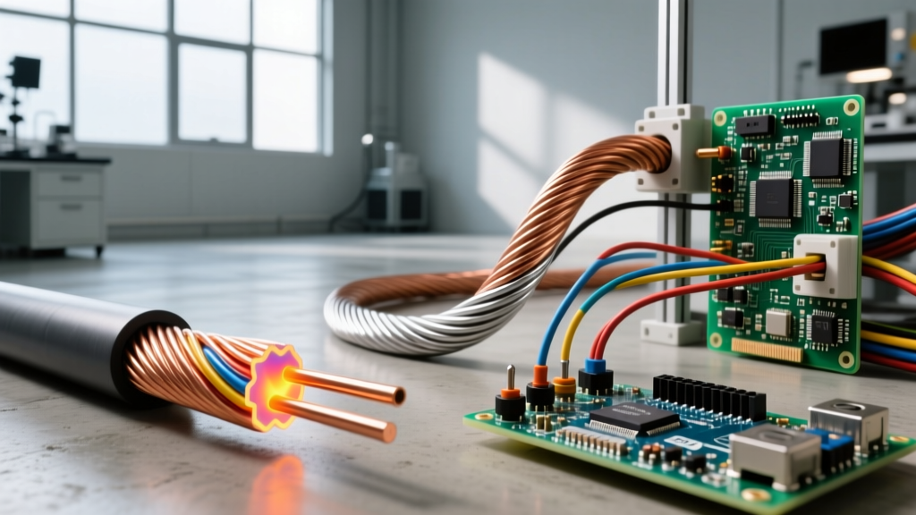
An AC current device is any electrical load designed to operate on alternating current, where electron flow periodically reverses direction at a standard frequency of 50Hz or 60Hz. Unlike simple DC resistors, AC current devices introduce complex impedance into a circuit. This changes how we calculate power, shifting the focus from simple voltage times current to managing phase angles, power factor, and apparent power (VA). The most common mistake makers and DIYers make is confusing RMS (Root Mean Square) current with peak current, or assuming that a device's wattage rating directly equals its volt-amp draw without accounting for power factor.
How AC Current Devices Actually Draw Power
When you look at the nameplate of an AC device, the voltage and current listed are almost always RMS values, not peak values. In a standard US 120V AC system, the RMS voltage is 120V, but the actual sine wave peaks at roughly 170V (120 x √2).
Think of RMS as the "equivalent DC heating value." If a 120V AC RMS space heater warms your garage, a 120V DC battery source would warm it exactly as much, even though the AC waveform's peak voltage actually spikes to 170V. This distinction is critical when selecting components like capacitors or diodes, which must be rated for the peak voltage, not the RMS voltage.
Furthermore, AC devices rarely draw current perfectly in phase with the voltage. Inductive loads (like motors) cause the current to lag, while capacitive loads cause it to lead. This phase shift means that the simple DC formula P = V × I no longer gives you real power in watts; it gives you apparent power in volt-amps (VA). To find true watts, you must multiply by the Power Factor (PF): W = V × I × PF. For a deep dive into the math behind this, the Electronics Tutorials guide on AC Power provides excellent phasor diagrams.
Load Profiles: Resistive vs. Inductive vs. Electronic
Not all AC current devices behave the same way. Sizing your wire and breakers requires knowing the specific load profile of the device you are wiring. The table below breaks down the four primary categories of AC loads you will encounter on the bench or in the panel.
| Device Type | Common Examples | Typical Power Factor (PF) | Inrush Current Multiplier | NEC Sizing Rule of Thumb |
|---|---|---|---|---|
| Resistive | Space heaters, incandescent bulbs, toasters | 1.0 (Unity) | 1x (None) | 100% of nameplate current |
| Inductive | AC motors, compressors, transformers, solenoids | 0.70 - 0.85 (Lagging) | 6x - 8x (Locked Rotor) | 125% of Full Load Current (FLC) |
| Capacitive | Power factor correction banks, long underground cables | Leading | High transient spike | Sized to kVAR, requires pre-charge |
| Non-Linear (Electronic) | SMPS, LED drivers, VFDs, computer PSUs | 0.50 - 0.95 (Distorted) | 2x - 3x (Capacitor charging) | 125% if continuous (>3 hrs) |
The Inrush Current Multiplier is where most DIY installations fail. An inductive AC motor might only draw 10A while running, but for the first 200 milliseconds of startup, it can pull 60A to 80A to overcome the locked rotor. If your breaker is not a motor-rated or HACR type, or if your wire gauge is too small to handle the voltage dip, the breaker will trip instantly every time the device starts.
Worked Numeric Example: Sizing a 120V Branch Circuit
Let’s look at what happens when you ignore power factor and inrush characteristics. Suppose you are wiring a dedicated 120V circuit for a commercial high-bay LED lighting array (a non-linear electronic AC current device).
The Mistake (Ignoring PF):
Many hobbyists will simply divide watts by volts: 1800W / 120V = 15A. They will then run 14 AWG wire and install a 20A breaker, assuming they have a safe 5A buffer.
The Correct Calculation (Accounting for AC Physics):
Because the LED drivers use switching power supplies, the current waveform is distorted, and the power factor is 0.85. We must calculate the actual current draw using apparent power.
- Find Apparent Power (VA): 1800W / 0.85 PF = 2,117 VA.
- Find True RMS Current: 2,117 VA / 120V = 17.64A.
- Apply Continuous Load Derating: Because commercial lights run for more than 3 hours, NEC Article 210.20(A) requires the branch circuit to be sized at 125% of the continuous load.
17.64A × 1.25 = 22.05A.
The Result:
Your actual required circuit capacity is 22.05A. A 20A breaker will eventually overheat and trip under continuous load. You must step up to a 25A or 30A breaker and use 10 AWG THHN copper wire (rated 35A in the 75°C column) to safely handle the true RMS current and satisfy code requirements. For more on how modern utilities handle these non-linear loads, Fluke's technical guide on True-RMS measurements explains how harmonic distortion physically heats up wiring.
Where You Meet This in Practice
Understanding the nuances of AC current devices isn't just academic; it solves specific, frustrating problems you will encounter in the field.
- Voltage Sag and Dimming Lights: When your workshop AC compressor (an inductive device) kicks on, the lights dim. This isn't because the motor is "stealing" voltage; it's because the massive inrush current (often 6x the running current) causes a temporary voltage drop across the impedance of your home's wiring. Upgrading the feeder wire or installing a soft-start module reduces this reactive inrush.
- Overheated Neutral Wires: In 3-phase commercial panels, non-linear AC current devices (like hundreds of computer power supplies) draw current in sharp, narrow pulses rather than smooth sine waves. These pulses create "triplen harmonics" (3rd, 9th, 15th) that do not cancel out in the neutral wire. Instead, they stack up. You can literally measure a neutral wire carrying more current than the phase wires, leading to melted neutral lugs if the wire wasn't oversized.
- Tripped Breakers on Generator Power: When running AC current devices on a portable inverter generator, the generator's output might have a slightly modified sine wave or higher total harmonic distortion (THD). Devices with strict peak-voltage tolerances (like some AC-to-DC switching supplies) will draw erratic current, causing the generator's internal breaker to trip even if the total wattage is well under the limit.
Ultimately, treating all AC current devices as simple resistive loads is a fast track to undersized wires, nuisance trips, and thermal failures. By respecting RMS values, calculating true apparent power, and applying the correct NEC sizing multipliers for inductive and continuous loads, your installations will run cool, safe, and code-compliant.