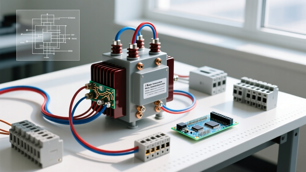

A 2-phase transformer is a magnetic device that steps voltage up or down across two alternating current waveforms, though in modern electrical systems, this term almost universally refers to a center-tapped split-phase transformer supplying two 120V legs from a single 240V source. It changes a single high-voltage utility distribution feed into two usable, opposing lower-voltage legs for residential and light commercial service panels. Most commonly, people confuse this with true 90-degree two-phase power (an obsolete early-AC standard) or three-phase delta and wye configurations.
The 'Two-Phase' Misnomer: Split-Phase vs. True Two-Phase
If you ask a utility lineman or a residential electrician for a '2 phase transformer,' they will hand you a standard single-phase, center-tapped distribution transformer. This is because true two-phase power—where two AC waveforms are separated by a 90° phase shift—was largely abandoned by the 1920s in favor of three-phase and single-phase split-phase systems.
What we call 'two-phase' today is actually split-phase. The utility feeds a single high-voltage phase (e.g., 7,200V) into the primary winding. The secondary winding is physically tapped in the exact middle. This center tap is bonded to ground, creating a neutral reference point. The two ends of the secondary winding then provide voltages that are 180° out of phase with each other relative to that neutral.
True 90-degree two-phase power still exists in a few legacy industrial pockets (like parts of Philadelphia) and specific railway traction systems. When engineers must interface modern 3-phase grids with legacy 2-phase loads, they use a specialized arrangement called a Scott-T transformer, which uses two single-phase transformers in a specific geometric wiring configuration to perform the phase conversion. But for 99% of bench, DIY, and residential work, you are dealing with a 180° split-phase center-tapped unit.
Standard 50 kVA Padmount Transformer Specifications
To ground this theory in reality, let us look at the exact specifications of the most common '2 phase' (split-phase) transformer you will encounter: the 50 kVA padmount or pole-top distribution transformer. These units step down distribution line voltage to the 120/240V used in your breaker panel.
| Parameter | Specification / Value | Field Notes |
|---|---|---|
| kVA Rating | 50 kVA | Max apparent power before thermal damage occurs. |
| Primary Voltage | 7,200V (or 12,470V / 19,920V) | Connected line-to-ground on the utility pole via a cutout fuse. |
| Secondary Voltage | 240V (Center-Tapped 120/240V) | Provides 120V (L-N) and 240V (L-L) simultaneously. |
| Full Load Secondary Current | 208.3 Amps | Calculated as 50,000 VA / 240V. |
| Impedance (%Z) | 2.2% to 2.5% | Determines available fault current for breaker AIC sizing. |
| Secondary Winding Configuration | Series (X1-X4 outer, X2-X3 tied) | X2 and X3 are internally tied and brought out as the X0 neutral. |
| Core & Coil Weight | ~650 lbs (295 kg) | Without mineral oil; total filled weight exceeds 900 lbs. |
Data sourced from standard IEEE C57.12.00 distribution transformer specifications and U.S. Department of Energy efficiency guidelines. Notice the secondary winding configuration: the transformer actually contains two separate 120V secondary coils. They can be wired in parallel for 120V-only high-current applications, but are wired in series for standard 120/240V split-phase service.
Worked Numeric Example: Loading, Imbalance, and Fault Current
Understanding how a center-tapped 2 phase transformer handles load imbalance is critical for sizing service entrance conductors and main breakers. Let us run the math on our 50 kVA, 240/120V transformer.
1. Maximum Line Current
The total capacity is 50,000 VA. Because the 240V loads span the entire secondary winding, the maximum continuous current on either Line 1 or Line 2 is:
I = VA / V = 50,000 / 240 = 208.3 Amps
2. Neutral Imbalance Calculation
Suppose your home has heavy 120V lighting on Line 1 and minimal 120V loads on Line 2.
Line 1 draws 160A.
Line 2 draws 80A.
Because the two legs are 180° out of phase, the currents do not add together in the neutral; they subtract. The neutral conductor only carries the difference between the two legs.
Neutral Current = |I_L1 - I_L2| = |160A - 80A| = 80 Amps
3. Available Fault Current (Short Circuit Math)
If a dead short occurs directly at the transformer secondary bushings, the impedance limits the current. Using the 2.2% impedance from our spec table:
I_fault = I_full_load / %Z = 208.3A / 0.022 = 9,468 Amps
This means your main panel breaker must have an AIC (Ampere Interrupting Capacity) rating of at least 10,000A (10kAIC) to safely clear a fault without exploding. Standard residential breakers are rated for 10kAIC, which perfectly aligns with this transformer size.
Where You Meet This in Practice
You will interact with the physical reality of the 2 phase (split-phase) transformer in three primary locations:
- The Utility Pole ('Pole Pig'): The cylindrical tank at the top of the pole. You will see a single high-voltage bushing on top (H1) and three low-voltage bushings on the side (X1, X2/X3 neutral, X4). The neutral is bonded to the pole ground wire.
- The Green Padmount Can: Found in modern subdivisions with underground utilities. Inside the locked cabinet, you will find the same transformer core submerged in mineral oil or biodegradable ester fluid, with heavy gauge copper wiring terminating in the secondary compartment.
- Autotransformers for Voltage Correction: If you are importing European 230V equipment to the US, or running US 240V equipment in the UK, you might use a 240V-to-120/240V autotransformer. Unlike the isolation transformer on the pole, an autotransformer shares a common winding. It will give you a center-tapped '2 phase' output, but it lacks the galvanic isolation of a true dual-winding transformer, meaning a fault on the primary side can energize your secondary neutral.
For a deeper dive into the vector mathematics of how these split-phase systems behave under reactive loads, the All About Circuits textbook chapter on Split-Phase Power provides excellent phasor diagrams.
Frequently Asked Questions
Can I use a 3-phase transformer to supply my 2-phase split-phase house?
No. A standard 3-phase transformer (Delta or Wye) outputs three waveforms separated by 120°. While you can tap a Delta transformer to get a 'high-leg' 120/240V split-phase output (often called a Red-Leg or High-Leg Delta), this requires specific 4-wire Delta configurations and strict NEC labeling rules. You cannot simply wire a standard 3-phase Wye transformer to act as a residential split-phase source without creating dangerous voltage imbalances and code violations.
Why does my multimeter read 240V across the two hot legs, but 120V to ground?
This is the defining characteristic of the center-tapped 2 phase transformer. Because the two 120V windings are wired in series, their voltages add up algebraically (120V + 120V = 240V) when measured across the outer limits (Line 1 to Line 2). When you measure from either outer leg to the center tap (which is bonded to ground), you are only measuring across one half of the secondary coil, yielding 120V.
What happens if the neutral wire breaks on the secondary side?
This is one of the most dangerous faults in residential wiring, known as an 'open neutral' or 'floating neutral.' Without the center tap bonded to ground to hold the reference voltage, the two 120V legs act as a voltage divider based on the resistance of the connected loads. A heavily loaded leg might drop to 40V, while a lightly loaded leg surges to 200V, instantly destroying electronics and appliances connected to the 120V circuits. Always verify neutral continuity before energizing a new service panel.