
Demystifying the Component: What Is a Potentiometer?
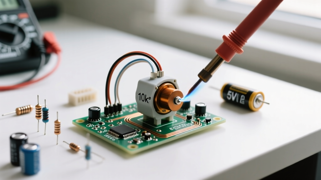
When makers and engineers ask, 'what is a potentiometer,' the most accurate technical definition is that it is a three-terminal variable resistor with a sliding or rotating contact. However, in practical circuit design, a potentiometer (often abbreviated as 'pot') functions fundamentally as a manually adjustable voltage divider. By moving a conductive wiper across a resistive track, you can precisely tap off a specific fraction of the input voltage or dynamically alter the resistance in a current path.
Understanding the internal mechanics, taper profiles, and correct wiring configurations is critical for any electronics hobbyist or professional. A miswired pot can lead to dead shorts, non-linear sensor readings, or catastrophic component failure. This tutorial breaks down the exact circuit applications, form factors, and troubleshooting techniques you need for reliable prototyping and PCB design.
Internal Mechanics and Taper Profiles
The resistive element inside a potentiometer is typically made from carbon composition, cermet (ceramic and metal), conductive plastic, or a wirewound resistance wire. The 'taper' of the potentiometer defines how the resistance changes relative to the physical position of the wiper. Selecting the wrong taper is a common beginner mistake that leads to poor user interfaces, especially in audio applications.
| Taper Type | Marking Code | Resistance at 50% Rotation | Primary Application |
|---|---|---|---|
| Linear | B (e.g., B10K) | 50% of total resistance | Position sensing, microcontroller inputs, voltage dividers |
| Audio (Logarithmic) | A (e.g., A10K) | ~10% to 20% of total resistance | Audio volume controls (matches human hearing perception) |
| Reverse Audio | C (e.g., C10K) | ~80% to 90% of total resistance | Specialized audio balance controls, tone stacks |
According to Wikipedia's comprehensive breakdown of potentiometers, the logarithmic taper is essential for audio because human perception of sound intensity is logarithmic, not linear. A linear pot used for volume control will appear to do nothing for the first 70% of its rotation, and then suddenly blast the volume in the final 30%.
Circuit Application 1: The Voltage Divider Configuration
The most common way to wire a potentiometer is as a three-terminal voltage divider. In this configuration, you apply a reference voltage (VCC) to one outer terminal, connect ground (GND) to the opposite outer terminal, and read the output voltage (Vout) from the center wiper pin.
Interfacing with Microcontroller ADCs
When using a pot to feed an analog-to-digital converter (ADC) on a microcontroller like the Arduino Uno (ATmega328P), the voltage divider math is straightforward: Vout = Vin × (R2 / (R1 + R2)). However, hardware engineers must account for the ADC's input impedance. As detailed in SparkFun's guide on voltage dividers, the load connected to the wiper will draw current, potentially causing voltage sag.
The ATmega328P datasheet recommends a source impedance of 10kΩ or less. This ensures the internal 14pF sample-and-hold capacitor charges fully within the 1.5 ADC clock cycles allocated for sampling. If you use a 1MΩ linear potentiometer, the ADC readings will fluctuate wildly and inaccurately due to incomplete capacitor charging. Always default to 10kΩ or 50kΩ pots for microcontroller analog inputs.
Pro-Tip: If your ADC readings are noisy, place a 0.1µF ceramic capacitor between the wiper terminal and ground. This creates a low-pass filter that smooths out high-frequency electrical noise without affecting the DC voltage reading.
Circuit Application 2: Variable Resistor (Rheostat) Mode
If you only need to vary resistance rather than voltage, you can wire the potentiometer as a two-terminal variable resistor, historically known as a rheostat. To do this, connect your circuit to the wiper and one of the outer terminals. The unused outer terminal is left floating or, preferably, tied directly to the wiper to prevent the circuit from opening if the wiper loses contact with the track.
Current Limiting and Tuning
This configuration is ideal for tuning the frequency of a 555-timer astable oscillator or manually adjusting the current limit for an LED. However, you must strictly observe the power rating of the component. A standard 16mm carbon film panel pot (like the Alpha RD901F series) is typically rated for only 0.1W to 0.2W. Using the formula P = I²R, pushing more than 100mA through a 10Ω setting will instantly overheat and destroy the carbon track. For high-current rheostat applications, you must use heavy-duty wirewound potentiometers, such as the Vishay 534B series, which can handle 1W to 5W of continuous power dissipation.
Real-World Prototyping: Selecting the Right Form Factor
The physical packaging of a potentiometer dictates how it integrates into your project enclosure or PCB layout.
- Panel Mount Pots: Features a threaded bushing and nut for mounting to a chassis. Common sizes are 16mm, 24mm, and 27mm. Ideal for user-facing knobs on synthesizers, amplifiers, and motor controllers.
- Trimpots (Trimming Potentiometers): Designed to be soldered directly to a PCB and adjusted with a small screwdriver during manufacturing or calibration. The Bourns 3386 series is a standard 1-turn cermet trimpot, while the Bourns 3296W is a 25-turn precision trimpot used for highly sensitive calibration tasks.
- Slide Potentiometers: Use a linear sliding mechanism instead of a rotary shaft. Commonly found in graphic equalizers and lighting mixing desks (e.g., Alps RS60 series).
Troubleshooting Common Potentiometer Failure Modes
Mechanical potentiometers are subject to physical wear and environmental degradation. Recognizing these failure modes is crucial for repairing vintage audio gear or debugging erratic sensor data.
Wiper Noise and 'Scratchy' Audio
Over time, the mechanical friction of the wiper generates microscopic carbon dust inside the housing. Combined with humidity, this dust creates localized short circuits or open dead-spots on the track, resulting in a 'scratchy' sound in audio amplifiers or sudden voltage spikes in sensor circuits. Furthermore, the metal wiper contact can oxidize, increasing contact resistance.
To resolve this, technicians use specialized contact cleaners. DeoxIT D5 is used to dissolve heavy oxidation on the metal contacts, while DeoxIT F5 (FaderLube) is specifically formulated to lubricate carbon and conductive plastic tracks without degrading them. Never use standard isopropyl alcohol on conductive plastic pots, as it can strip the factory-applied lubricants and ruin the component.
Mechanical Binding and Shaft Play
In cheap potentiometers, the internal metal tab that tensions the wiper can bend out of shape, causing the wiper to lift off the resistive track entirely at certain angles. This results in an 'open circuit' state where the resistance spikes to infinity. If a pot exhibits mechanical binding or excessive shaft wobble, it must be replaced; internal mechanical tensioning is rarely repairable in modern sealed units.
Digital Alternatives: When Mechanical Pots Fall Short
While answering 'what is a potentiometer' usually implies a mechanical component, modern circuit design frequently replaces them with digital potentiometers (digipots). As explored in Analog Devices' technical articles on digital pots, these integrated circuits use an internal resistor ladder and CMOS switches to emulate a wiper, controlled via SPI or I2C protocols.
Chips like the Microchip MCP4131 or the ADI AD5292 offer massive advantages in automated systems: they do not suffer from mechanical wear, they are immune to vibration-induced wiper bounce, and they can be recalibrated by software on every power-up. However, digipots have strict limitations regarding the voltage rails they can handle (usually restricted to the logic supply voltage, like 3.3V or 5V) and cannot pass audio signals that swing below ground without specialized dual-supply architectures. For high-voltage or high-fidelity audio applications, the traditional mechanical potentiometer remains the undisputed standard.