
The Core Question: What Does the Potentiometer Do?
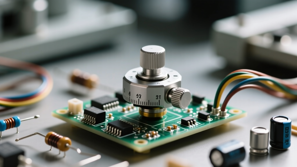
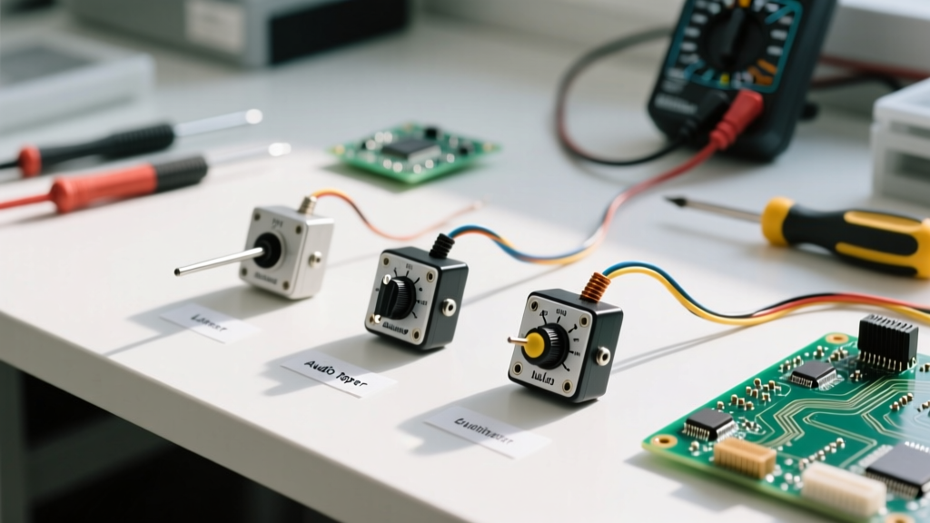
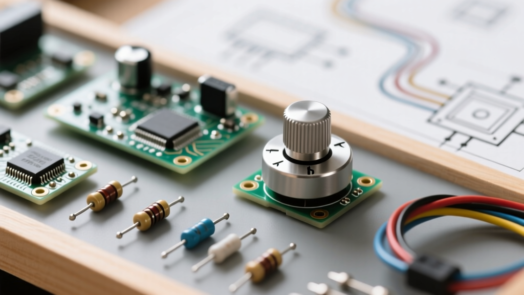
If you have just unboxed a beginner electronics kit or an Arduino starter bundle, you have likely found a small, circular component with three metal pins and a rotating shaft. This is the potentiometer (often abbreviated as 'pot'). But beyond simply turning a knob, what does the potentiometer do in the context of circuit prototyping?
At its most fundamental level, a potentiometer is an adjustable voltage divider. While it can be used as a variable resistor (rheostat) to limit current, its primary role in beginner microcontroller projects is to provide a user-adjustable analog voltage signal. This allows you to translate physical, rotational human input into an electrical value that a microcontroller's Analog-to-Digital Converter (ADC) can read, enabling you to control LED brightness, motor speed, or audio volume.
Inside the Casing: Anatomy of a Carbon Track Pot
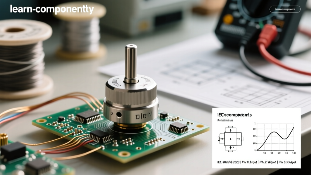
To understand how it works, you need to look inside the metal or plastic casing. The typical 10KΩ rotary potentiometer found in educational kits relies on a resistive carbon composition track shaped like a horseshoe (roughly 270 degrees of rotation).
- The Resistive Track: A strip of carbon or cermet material with a fixed total resistance (e.g., 10,000 ohms) between the two outer terminals.
- The Wiper: A spring-loaded metal contact attached to the central shaft. As you turn the knob, the wiper slides along the carbon track.
- The Terminals: Three pins. Pin 1 and Pin 3 connect to the opposite ends of the resistive track. Pin 2 connects directly to the wiper.
As the wiper moves closer to Pin 1, the resistance between Pin 1 and Pin 2 decreases, while the resistance between Pin 2 and Pin 3 increases. The sum of these two resistances always equals the total rated resistance of the pot.
Decoding the Pins: Wiring for Voltage Division
According to foundational electronics principles outlined by Electronics Tutorials, wiring a potentiometer as a voltage divider requires all three pins. You apply a reference voltage (like 5V from an Arduino) across the outer pins, and the wiper outputs a fraction of that voltage.
| Terminal | Common Label | Connection in a 5V Microcontroller Circuit | Function |
|---|---|---|---|
| Pin 1 (CCW) | Ground / GND | Connected to Microcontroller GND | Sets the 0V baseline reference |
| Pin 2 (Center) | Wiper / VOUT | Connected to Analog Input (e.g., A0) | Outputs the variable voltage (0V to 5V) |
| Pin 3 (CW) | VCC / V+ | Connected to 5V or 3.3V Power | Sets the maximum voltage ceiling |
Pro-Tip for Prototyping: If you wire Pin 1 and Pin 3 backward, the circuit will still work perfectly, but the rotational logic will be inverted (turning clockwise will decrease the value instead of increasing it). Simply swap the outer wires in your code or on the breadboard to fix this.
Linear vs. Audio Taper: Which One is in Your Kit?
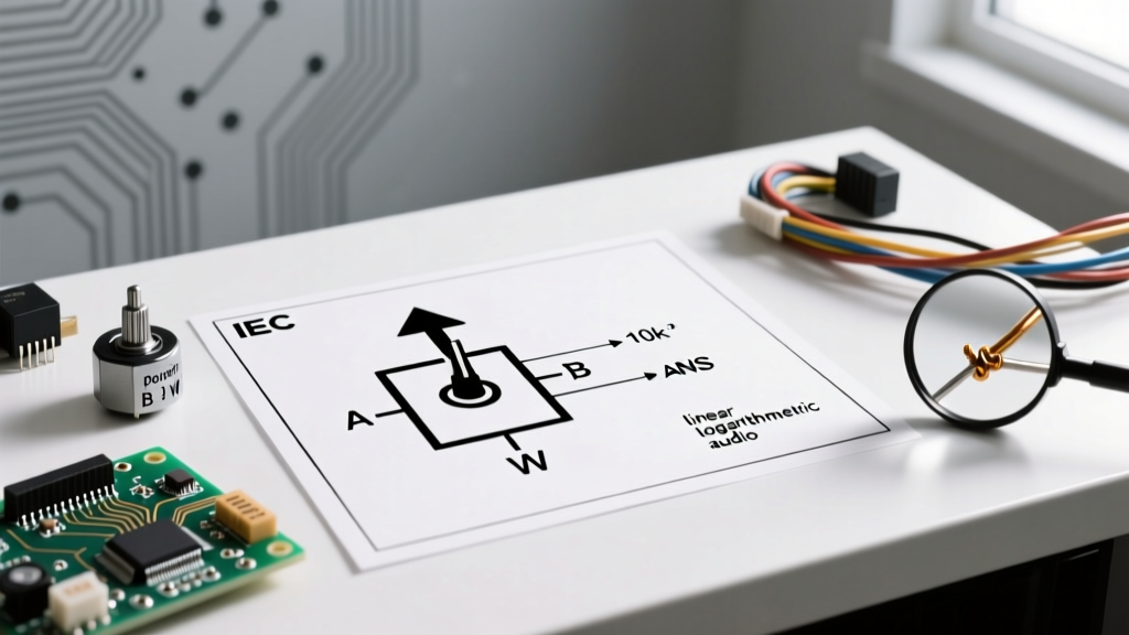
Not all potentiometers change resistance at the same rate. The relationship between the shaft angle and the resistance is called the 'taper'. Beginner kits almost exclusively include Linear Taper potentiometers, but it is vital to know the difference.
Linear Taper (Marked with 'B')
A 10KΩ linear pot (often stamped B10K) changes resistance at a constant, uniform rate. At exactly 50% rotation, the resistance from the wiper to either end is exactly 5KΩ. This is mandatory for microcontroller inputs because microcontrollers expect a 1:1 linear correlation between physical position and digital data.
Audio / Logarithmic Taper (Marked with 'A')
An audio pot (stamped A10K) follows a logarithmic curve. Human hearing perceives volume logarithmically, so an audio pot spends most of its physical rotation making small resistance changes at the lower end, and rapid changes at the higher end. If you accidentally use an 'A' taper pot for an Arduino joystick or dial, your software readings will feel incredibly sluggish at one end and hyper-sensitive at the other.
Practical Application: Reading Analog Values with Arduino
When you connect the wiper to an analog pin on an Arduino Uno, the microcontroller's 10-bit ADC maps the incoming 0-5V signal to an integer range between 0 and 1023. As detailed in the official Arduino Analog Input documentation, reading this value requires just one line of code: int sensorValue = analogRead(A0);
Solving the 'Jittery Reading' Problem
A common frustration for beginners is opening the Serial Monitor and seeing the analog value jump erratically (e.g., 512, 515, 509, 514) even when the knob is completely still. This is caused by two factors:
- ADC Noise: Microcontrollers are sensitive to electromagnetic interference and power rail ripple.
- Wiper Bounce: The physical carbon track has microscopic imperfections, and the spring-loaded wiper can vibrate slightly.
The Hardware Fix: Solder or place a 0.1µF ceramic capacitor between the wiper pin (Pin 2) and Ground. This creates a low-pass filter that smooths out high-frequency electrical noise before it reaches the microcontroller.
The Software Fix: Implement an Exponential Moving Average (EMA) in your code to mathematically smooth the incoming data stream, discarding sudden, impossible spikes.
Advanced Usage: The Rheostat Configuration
Sometimes you do not want a voltage divider; you want to manually limit current to an LED or a small motor. In this scenario, you use the potentiometer as a variable resistor, or rheostat. You only need two pins: one outer pin and the center wiper.
However, SparkFun's guide on voltage dividers and resistors highlights a critical failure mode in cheap carbon pots: the wiper can momentarily lose physical contact with the carbon track due to dust or vibration. If the wiper lifts, the circuit becomes an 'open' (infinite resistance), which could cause a microcontroller pin to float unpredictably or cause a motor driver to spike.
The Expert Solution: Always jumper the unused outer terminal directly to the wiper terminal. If the wiper lifts off the track, the current will seamlessly flow through the jumper wire to the outer terminal, maintaining the maximum resistance of the pot rather than breaking the circuit entirely.
Power Ratings and Safety Limitations
The standard rotary potentiometer in a beginner kit is rated for 0.125W (1/8 Watt) or 0.25W (1/4 Watt) of power dissipation. They are designed for low-current signal processing, not high-power load driving.
Never wire a standard kit potentiometer in series with a high-draw component like a 12V DC motor or a high-power LED strip. The current will exceed the carbon track's thermal limits, literally burning the carbon off the plastic backing and permanently destroying the component as an open circuit. For high-power applications, the potentiometer should only be used to feed a low-current signal into an op-amp, a MOSFET gate, or a motor controller IC, which then handles the heavy current load.
Summary
Understanding what the potentiometer does transforms it from a simple 'knob' into a versatile bridge between the physical and digital worlds. By mastering its pinout, recognizing the linear taper, and applying basic hardware debouncing techniques, you can extract clean, reliable analog data for any DIY microcontroller project.