
Why Standard Sensors Fail in Harsh Environments
When prototyping on a dry workbench, the standard HC-SR04 ultrasonic sensor is a staple for distance measurement. However, the moment you deploy it outdoors, inside a humid greenhouse, or above a water tank, it inevitably fails. The exposed 40kHz piezoelectric mesh on standard sensors traps moisture, leading to short circuits, acoustic dampening, and permanent corrosion. For outdoor DIY projects, rain barrels, or marine applications, you must upgrade to a dedicated waterproof ultrasonic sensor.
In this beginner tutorial, we will deep-dive into the JSN-SR04T and AJ-SR04M models. We will cover the physics of their acoustic blind zones, how to safely interface them with 3.3V and 5V microcontrollers, and how to write non-blocking code that prevents your Arduino or ESP32 from freezing during a timeout.
Anatomy of the JSN-SR04T Waterproof Ultrasonic Sensor
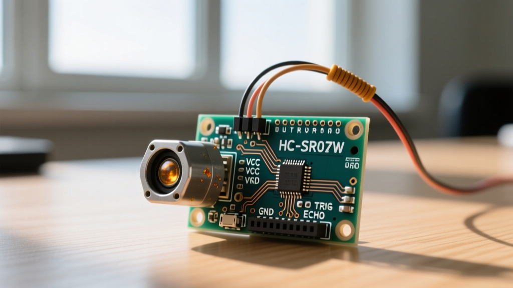
Unlike the integrated HC-SR04, the JSN-SR04T separates the acoustic transducer from the control PCB. The transducer is a sealed, metal-mesh-capped cylinder rated for IP67 water resistance. It connects to the main control board via a 2.5-meter shielded ribbon cable. This physical separation allows you to mount the control board inside a dry, sealed NEMA enclosure while routing the transducer cable through a waterproof gland into a rain tank or outdoor environment.
The control board operates at 5V and utilizes the same 4-pin interface as the standard HC-SR04: VCC, Trig, Echo, and GND. However, the internal timing circuitry is optimized for the longer cable runs and the specific acoustic impedance of the waterproof transducer cap.
The Physics of the 25cm Blind Zone
The most critical specification beginners overlook is the blind zone. Standard sensors can read objects as close as 2cm. The JSN-SR04T, however, has a minimum reading distance of 20cm to 25cm. Why? When the transducer emits a burst of 40kHz sound waves, the physical metal diaphragm continues to vibrate (or "ring") for a few milliseconds after the electrical signal stops. If an object is closer than 20cm, the returning echo hits the diaphragm while it is still vibrating from the initial pulse. The sensor's comparator circuit cannot distinguish the echo from the initial ringing, resulting in a false reading of 0cm or a complete timeout. Always mount your waterproof sensor at least 30cm above your target surface.
Hardware Wiring: Navigating 5V and 3.3V Logic
Wiring the sensor to a 5V Arduino Uno or Nano is straightforward. Connect VCC to 5V, GND to GND, Trig to Digital Pin 9, and Echo to Digital Pin 10. However, modern electronics frequently rely on 3.3V microcontrollers like the ESP32, Raspberry Pi Pico, or SAMD21 boards. Never connect the JSN-SR04T Echo pin directly to a 3.3V GPIO. The sensor outputs a 5V HIGH signal on the Echo pin, which will permanently damage the logic gates of a 3.3V microcontroller.
For a comprehensive understanding of voltage tolerances, refer to the SparkFun guide on Logic Levels, which explains why exceeding the absolute maximum ratings of CMOS chips leads to silicon degradation.
Designing a Voltage Divider for ESP32
To safely step down the 5V Echo signal to a safe 3.3V, you must build a simple resistor voltage divider. Using Ohm's Law, we can select standard resistor values:
- R1 (Series Resistor): 1kΩ (Connect between Sensor Echo and ESP32 GPIO)
- R2 (Pull-down Resistor): 2kΩ (Connect between ESP32 GPIO and GND)
The formula is Vout = Vin * (R2 / (R1 + R2)). Plugging in our values: 5V * (2000 / 3000) = 3.33V. This safely limits the voltage entering your ESP32 pin. Alternatively, you can purchase the AJ-SR04M variant, which is a specialized version of the waterproof sensor featuring an onboard logic-level shifter and a native 3.3V operating mode, eliminating the need for external resistors.
Writing Robust Arduino Code with NewPing
Many beginner tutorials use the native Arduino pulseIn() function to measure the Echo pin's HIGH duration. This is a critical mistake for production or multi-sensor code. pulseIn() is a blocking function; if the sound wave scatters and no echo returns, the microcontroller will freeze and wait for the default timeout (often up to 1000ms or more), completely halting your loop() and ruining Wi-Fi or LED timing tasks.
Instead, use the NewPing Library by Tim Eckel. NewPing utilizes hardware timers to measure the pulse in the background, allowing your code to remain non-blocking. For more on optimizing ESP32 and Arduino sensor loops, Random Nerd Tutorials provides excellent architectural advice on handling ultrasonic interrupts.
#include <NewPing.h>

#define TRIGGER_PIN  9
#define ECHO_PIN     10
#define MAX_DISTANCE 400 // Max distance in cm (JSN-SR04T max is ~450cm)

// Initialize the NewPing object
NewPing sonar(TRIGGER_PIN, ECHO_PIN, MAX_DISTANCE);

void setup() {
  Serial.begin(115200);
  Serial.println("Waterproof Ultrasonic Sensor Initialized.");
}

void loop() {
  // ping_cm() returns 0 if no echo is received (out of range or blind zone)
  unsigned int distance = sonar.ping_cm();

  if (distance == 0) {
    Serial.println("Out of range or inside 25cm blind zone.");
  } else {
    Serial.print("Distance: ");
    Serial.print(distance);
    Serial.println(" cm");
  }

  // Wait 50ms between pings (approx 20Hz).
  // Sound travels ~343m/s, so 50ms prevents overlapping echoes.
  delay(50);
}
Real-World Failure Modes and Troubleshooting
Even with a waterproof transducer, environmental physics can cause erratic readings. Here are the most common failure modes encountered in field deployments:
1. The Waveguide Effect in Narrow Pipes
If you are measuring the water level inside a narrow PVC standpipe (e.g., a 2-inch diameter tube), the 40kHz sound waves will bounce off the interior walls of the pipe multiple times before returning to the sensor. This multipath reflection creates "ghost" echoes, causing the sensor to report distances that are 2x or 3x the actual distance. Solution: Use a wider diameter pipe (minimum 4 inches) or mount the sensor on a flared acoustic horn to focus the beam strictly downward.
2. Condensation on the Transducer Mesh
While the sensor is waterproof against splashing and submersion, high-humidity environments (like a sealed rain barrel at night) can cause micro-condensation to form on the inside of the metal mesh. Water has a vastly different acoustic impedance than air, and a layer of condensation will absorb the 40kHz frequency, resulting in weak or missing echoes. Solution: Apply a very thin, careful layer of hydrophobic nano-coating to the exterior mesh, or ensure the enclosure has a silica gel desiccant pack to manage internal humidity.
3. Cable Capacitance and Signal Degradation
The JSN-SR04T comes with a 2.5m cable. If you extend this cable using standard unshielded wire to reach 5 meters or more, the parasitic capacitance of the long wire will degrade the sharp rising edge of the 5V Trigger pulse. The control board may fail to register the trigger, resulting in zero readings. Solution: If extending the cable, use shielded Cat5e Ethernet cable, tying the shield to GND at the control board side only to prevent ground loops.
Sensor Comparison Matrix
Choosing the right waterproof sensor depends on your microcontroller and environmental constraints. Use the table below to make your hardware decision:
| Feature | Standard HC-SR04 | JSN-SR04T (V2.0) | AJ-SR04M (3.3V Native) |
|---|---|---|---|
| Waterproof Rating | None (Exposed PCB) | IP67 (Transducer Only) | IP67 (Transducer Only) |
| Operating Voltage | 5V DC | 5V DC | 3.3V to 5V DC |
| Logic Level Output | 5V | 5V (Requires Divider for 3.3V) | 3.3V (Safe for ESP32/Pico) |
| Blind Zone | ~2 cm | ~25 cm | ~20 cm |
| Max Range | 400 cm | 450 cm | 400 cm |
| Best Use Case | Indoor robotics, dry benches | Outdoor tanks, 5V Arduinos | ESP32 IoT nodes, 3.3V systems |
Final Thoughts on Deployment
Upgrading to a waterproof ultrasonic sensor immediately elevates the reliability of your outdoor electronics projects. By respecting the 25cm acoustic blind zone, implementing proper logic-level shifting for 3.3V microcontrollers, and utilizing non-blocking timer libraries like NewPing, you will achieve industrial-grade reliability on a hobbyist budget. Always remember that while the transducer is waterproof, the control board is not—proper enclosure sealing and conformal coating are the final steps to ensuring your DIY sensor network survives the elements for years to come. For further reading on microcontroller best practices, consult the Official Arduino Library Documentation to explore advanced timing interrupts.