
Every electrical system relies on a delicate balance between two fundamental components: the pathway for electron flow and the barrier that keeps it contained. When troubleshooting wiring faults, junior technicians often focus exclusively on continuity, resistance, and voltage drop. However, seasoned electrical engineers know that the true culprit behind intermittent trips, ground faults, and catastrophic arcs usually lies at the intersection of the conductor and insulator. While the copper or aluminum core does the heavy lifting of current transmission, the dielectric barrier is the unsung hero that maintains system integrity. When this barrier compromises, the results range from nuisance GFCI trips to devastating switchgear explosions.
In this comprehensive troubleshooting guide, we will dissect the failure modes of wire insulation, explore advanced diagnostic testing methodologies, and provide a definitive framework for isolating dielectric breakdowns in both low-voltage and medium-voltage applications.
The Physics of Dielectric Breakdown: Why Insulators Fail
To troubleshoot effectively, one must understand the physics of insulation failure. An insulator is not a perfect barrier; it is simply a material with a highly restricted bandgap that prevents valence electrons from entering the conduction band under normal conditions. However, when subjected to excessive electrical stress, thermal cycling, or environmental contamination, the molecular structure degrades.
Dielectric breakdown occurs when the applied electric field (measured in kV/mm) exceeds the material's dielectric strength. At this threshold, electrons are violently torn from their atomic bonds, creating a conductive plasma channel through the insulation. In real-world troubleshooting, we rarely see instantaneous dielectric breakdown unless there is a massive voltage surge (like a lightning strike). Instead, we deal with partial degradation—micro-fractures, moisture ingress, and chemical tracking that slowly erode the insulator's resistance over months or years.
Field Diagnostics: Moving Beyond the Multimeter
A standard digital multimeter (DMM) is virtually useless for troubleshooting compromised insulation. A DMM typically outputs between 3V and 9V during resistance testing. This low voltage cannot bridge the gap across micro-fractures or force moisture-laden contaminants to reveal their conductive nature. To properly evaluate the conductor and insulator health, you must employ high-potential testing.
Step 1: Insulation Resistance (IR) and Polarization Index
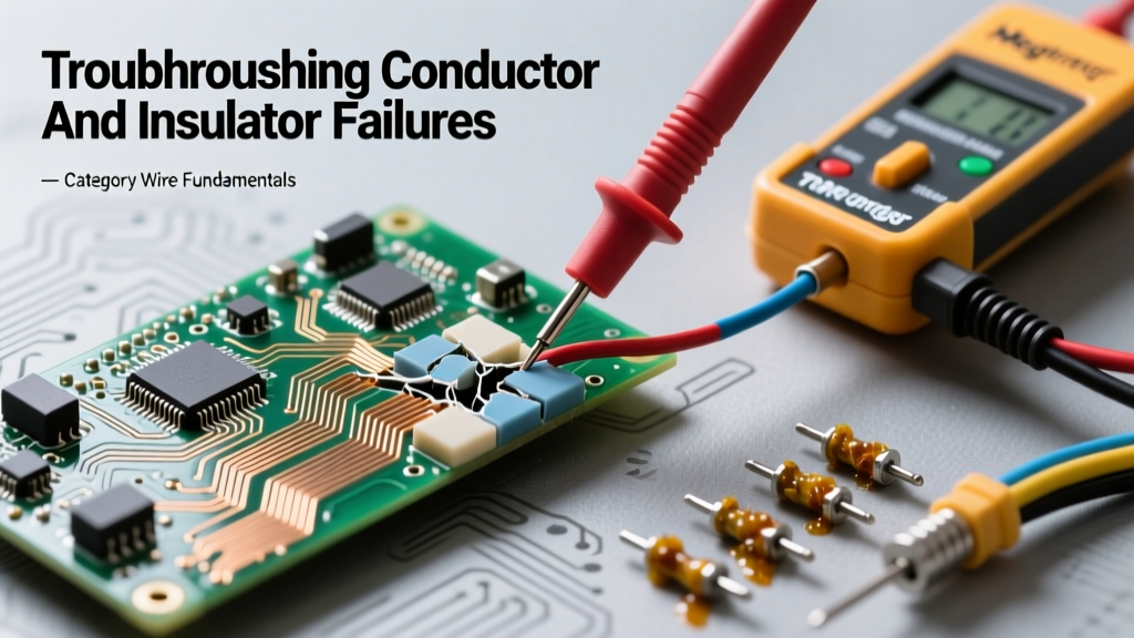
Using a Megohmmeter (commonly referred to by the brand name Megger), you apply a high DC voltage—typically 500V for low-voltage circuits and up to 5000V for medium-voltage feeders. According to Megger's insulation testing guidelines, you are not just looking for a static resistance value; you are looking for capacitance absorption over time.
For critical motors and long cable runs, troubleshooters use the Polarization Index (PI). The PI is the ratio of the 10-minute IR reading to the 1-minute IR reading.
- PI < 1.0: Dangerous. Indicates severe moisture ingress or heavy contamination. The insulation is acting like a capacitor that is absorbing charge and leaking heavily.
- PI 1.0 - 2.0: Questionable. Requires further investigation and potential cleaning/drying.
- PI > 2.0: Excellent. The dielectric material is polarizing correctly and blocking leakage current.
Step 2: Time-Domain Reflectometry (TDR)
When an IR test confirms a fault, but the cable is buried or routed through extensive conduit, finding the physical location of the fault is a nightmare. TDR acts as radar for cables. By sending a high-frequency pulse down the conductor and measuring the reflection, a TDR can pinpoint impedance mismatches caused by water ingress, crushed insulation, or degraded splices within inches, even on runs exceeding 10,000 feet.
Material-Specific Degradation Profiles
Troubleshooting requires knowing your materials. The way a PVC jacket fails is fundamentally different from how an XLPE or PTFE dielectric degrades. Below is a diagnostic matrix for common wire insulators:
| Insulator Material | Max Rated Temp | Dielectric Strength | Primary Failure Mode | Visual Troubleshooting Clues |
|---|---|---|---|---|
| PVC (Polyvinyl Chloride) | 70°C - 105°C | ~40 kV/mm | Thermal embrittlement, Plasticizer migration | Cracking, white powdery residue, stiff jacket |
| XLPE (Cross-Linked Polyethylene) | 90°C | ~50 kV/mm | Water treeing, Electrical treeing | Hidden internal dendrites (requires PD testing to detect) |
| PTFE (Teflon) | 250°C | ~60 kV/mm | Creepage under extreme mechanical stress | Cold flow deformation, scuffing near termination points |
| EPR (Ethylene Propylene Rubber) | 90°C | ~30 kV/mm | Ozone cracking, UV degradation | Surface checking, chalky oxidation, longitudinal splits |
The Silent Killers: Treeing and Partial Discharge
In medium and high-voltage troubleshooting, the most insidious failure mode affecting the conductor and insulator interface is 'treeing'. This phenomenon is heavily documented in IEEE Std 400 regarding shielded power cable systems.
Water Treeing vs. Electrical Treeing
Water Treeing occurs primarily in XLPE cables exposed to moisture. Microscopic droplets of water align with the electric field, creating fern-like dendritic structures that slowly penetrate the dielectric. Water trees do not cause immediate failure, but they severely distort the local electric field.
Electrical Treeing is the fatal successor to water treeing. Once the dielectric is sufficiently compromised, localized partial discharges (micro-sparks) begin to burn hollow, branching channels through the solid insulation. Once an electrical tree bridges the gap between the conductor and the ground shield, catastrophic failure is imminent.
Troubleshooting Tip: You cannot see treeing with the naked eye until the cable has already failed. To troubleshoot suspected treeing in energized cables, you must use Partial Discharge (PD) sensors, such as High-Frequency Current Transformers (HFCT) clamped around the ground wire, to detect the electromagnetic pulses emitted by the micro-sparks.
Thermal Degradation and the Arrhenius Equation
Many insulation failures are misdiagnosed as electrical surges when the root cause is thermal. The Arrhenius equation dictates the rate of chemical degradation in polymers. As a rule of thumb in electrical troubleshooting, for every 10°C a cable operates above its rated temperature, the lifespan of the insulator is halved.
"When evaluating historical failures in switchgear and motor control centers, always cross-reference the ambient temperature logs with the cable ampacity derating factors. A 90°C THHN wire routed through a 50°C boiler room without proper derating is operating in a state of accelerated thermal suicide."
If you are troubleshooting a recurring ground fault in a high-ambient environment, inspect the insulator for 'thermal hardening'. If the PVC or XLPE feels like rigid glass rather than flexible plastic, the polymer chains have cross-linked excessively due to heat, making the insulator highly susceptible to mechanical vibration and subsequent cracking.
Actionable Remediation and Prevention Matrix
When you have isolated a fault to the insulator, use this decision matrix to determine the correct remediation path:
- Symptom: Low IR reading (< 1 Megohm) on a motor feeder, PI < 1.0.
Root Cause: Moisture ingress in conduit.
Action: Do not apply high-voltage AC (Hipot). Flush conduit with denatured alcohol, apply directed hot air, and re-test until PI > 2.0. - Symptom: Intermittent GFCI trips on outdoor UF-B cable, TDR shows impedance anomaly mid-run.
Root Cause: Mechanical damage (shovel strike) compromising the jacket and allowing soil electrolytes to bridge the conductor and insulator.
Action: Excavate and replace the damaged section using a resin-filled underground splice kit. Do not rely on heat-shrink alone for direct-burial environments. - Symptom: Surface tracking and carbon scoring on termination points in a dusty manufacturing plant.
Root Cause: Conductive dust mixing with ambient humidity, creating a leakage path across the surface of the insulator.
Action: Clean with specialized electrical contact cleaner. Apply RTV silicone coating to increase surface hydrophobicity and prevent future tracking.
Conclusion: Respecting the Dielectric
Troubleshooting electrical systems requires a paradigm shift from simply measuring current flow to actively interrogating the barriers that contain it. By utilizing advanced diagnostics like Polarization Index testing, TDR, and Partial Discharge analysis, technicians can predict and prevent failures before they result in downtime or danger. Always consult the NETA Acceptance Testing Specifications for baseline testing values, and remember that maintaining the health of the insulator is just as critical as sizing the conductor.