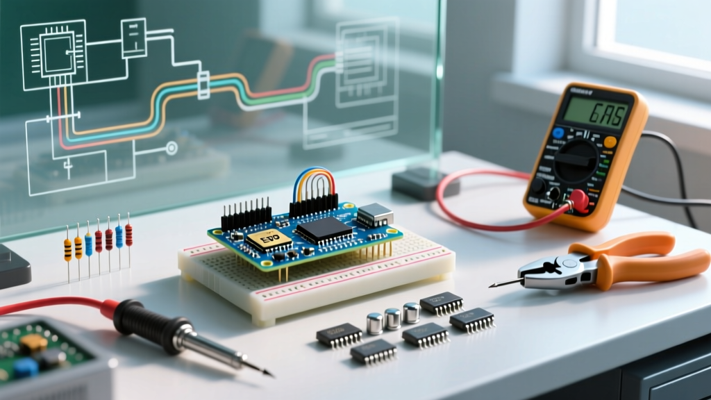

Unpacking Your Starter Kit: Why Test a Potentiometer?
When you crack open your first Arduino or Raspberry Pi starter kit, you will inevitably find a small bag of variable resistors. Whether it is a rotary dial with a knurled plastic shaft or a tiny blue square trimmer with a brass screw, these components are essential for reading analog inputs, controlling motor speeds, or dimming LEDs. But what happens if your analog readings are jumping erratically, or the component feels physically loose? If you are sitting at your workbench wondering how do you test a potentiometer before wiring it to a sensitive microcontroller pin, you are in the right place.
Testing a potentiometer (often abbreviated as a "pot") requires nothing more than a basic digital multimeter (DMM) and a fundamental understanding of its internal anatomy. In this guide, we will walk through the exact diagnostic steps to verify total resistance, test the wiper sweep, and identify the dreaded "wiper noise" that plagues cheap carbon-film components found in beginner kits.
The Anatomy of a Beginner Kit Potentiometer
Before touching your multimeter probes to the metal pins, you must understand what is happening inside the plastic housing. According to Electronics Tutorials, a potentiometer is essentially a three-terminal resistor with a sliding or rotating contact that forms an adjustable voltage divider.
Most beginner kits include one of two types:
- Rotary Potentiometers (e.g., Alpha 16mm): Feature a long shaft meant for user interaction (like a volume knob). They usually have a resistance of 10KΩ or 50KΩ.
- Trimpots (e.g., Bourns 3386P): The small blue, square components with a single slotted screw on top. These are meant for "set-and-forget" calibration on a breadboard or PCB.
Regardless of the physical packaging, the electrical pinout remains identical across almost all standard single-turn potentiometers:
- Pin 1 (CCW): The counter-clockwise terminal. Usually connected to Ground (GND).
- Pin 2 (Wiper): The middle terminal. This is the moving contact that slides across the resistive element. This connects to your microcontroller's Analog-to-Digital Converter (ADC) pin.
- Pin 3 (CW): The clockwise terminal. Usually connected to Voltage (VCC / 5V / 3.3V).
Tools Required for the Test
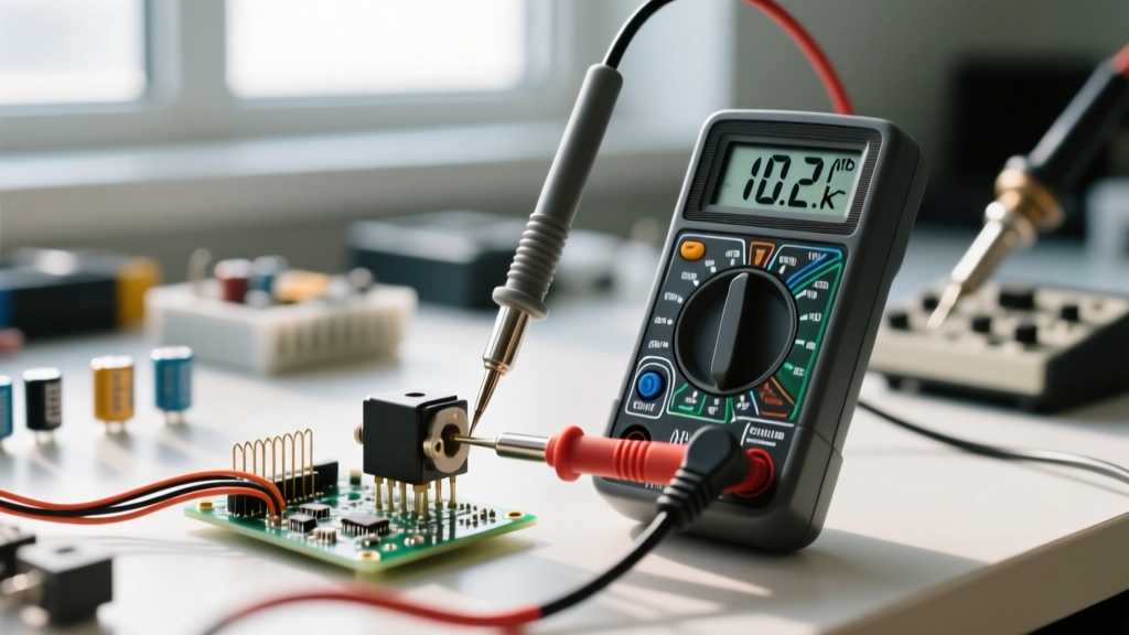
You do not need an oscilloscope or an LCR meter to diagnose a standard kit potentiometer. A standard auto-ranging or manual-ranging Digital Multimeter is perfectly adequate. As noted in Fluke's guide to measuring resistance, ensuring your test leads are in the correct ports (COM and Ω/V/mA) and the dial is set to the Ohms (Ω) symbol is the critical first step.
Recommended Gear:
- Digital Multimeter (e.g., AstroAI AM33D or UNI-T UT61E)
- Alligator clip test leads (highly recommended to free up your hands while turning the shaft)
- A small flathead screwdriver (if testing a blue Bourns trimpot)
Step 1: Measuring Total Resistance (Pins 1 and 3)
The first test establishes the baseline health of the internal resistive track. We need to verify that the carbon or cermet film has not snapped or degraded internally.
The Testing Procedure
- Set your multimeter to the Resistance (Ω) setting. If your DMM is manual-ranging and you are testing a 10KΩ pot, set the dial to the 20KΩ range.
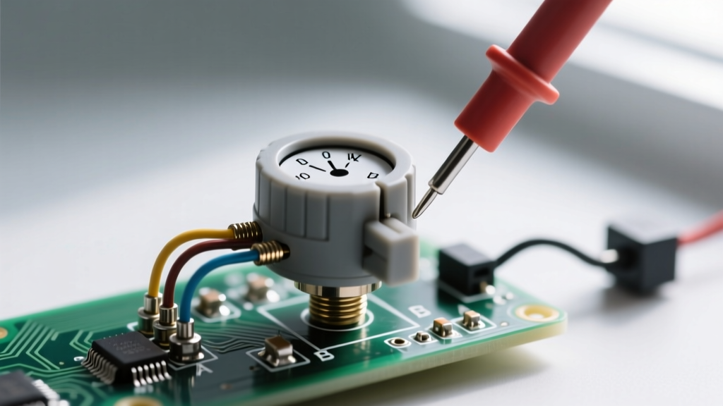
- Place one probe on Pin 1 and the other probe on Pin 3. (Polarity does not matter for resistance).
- Read the display.
Interpreting the Results
If you are testing a standard 10KΩ potentiometer (often marked with "B103" or "10K" on the casing), your multimeter should read somewhere between 8,500 Ω and 11,500 Ω. Beginner kit potentiometers are typically manufactured with a ±20% tolerance. If your meter reads "OL" (Over Limit) or infinity, the internal resistive track is broken, and the component is dead. If it reads near 0 Ω, the component is shorted internally and must be discarded.
Step 2: Testing the Wiper Sweep (The Crucial Step)
Now we answer the core of how do you test a potentiometer for functional movement. This step verifies that the wiper (Pin 2) maintains continuous electrical contact with the resistive track as it moves from one end to the other.
The Testing Procedure
- Move your multimeter probes to Pin 1 and Pin 2 (the Wiper).
- Turn the shaft (or screw) fully counter-clockwise. The resistance should drop to near 0 Ω (usually 1 Ω to 5 Ω due to the internal metal contacts).
- Slowly and smoothly rotate the shaft fully clockwise while watching the multimeter display.
- The resistance value should climb steadily and smoothly until it reaches the total resistance value you recorded in Step 1.
Understanding Tapers: Linear vs. Audio
As you sweep the wiper, pay attention to how the numbers climb. This reveals the "taper" of the potentiometer, a vital concept detailed in SparkFun's Voltage Divider tutorial. Most microcontroller kits use Linear Tapers (marked with a "B", like B10K), but audio kits use Logarithmic/Audio Tapers (marked with an "A", like A10K).
| Shaft Position | Linear Taper (B10K) Expected Reading | Audio Taper (A10K) Expected Reading |
|---|---|---|
| 0% (Fully CCW) | ~0 Ω to 5 Ω | ~0 Ω to 5 Ω |
| 25% Rotation | ~2,500 Ω | ~400 Ω to 600 Ω |
| 50% (Center Detent) | ~5,000 Ω | ~1,200 Ω to 1,800 Ω |
| 75% Rotation | ~7,500 Ω | ~3,500 Ω to 4,500 Ω |
| 100% (Fully CW) | ~10,000 Ω | ~10,000 Ω |
Note: If your linear potentiometer jumps wildly or drops back to zero in the middle of the sweep, the carbon track is heavily worn or contaminated.
Step 3: Checking for "Wiper Noise" and Dead Spots
A multimeter's sampling rate is relatively slow, meaning it might miss micro-second disconnects as the wiper slides over microscopic pits in the carbon track. In a microcontroller environment, this manifests as "wiper noise"—sudden, massive spikes in your ADC readings.
To test for dead spots with a DMM:
- Keep the probes on Pin 1 and Pin 2.
- Turn the shaft very slowly millimeter by millimeter.
- Watch for any sudden drops to "OL" or erratic jumping (e.g., jumping from 3,000 Ω to 8,000 Ω and back to 3,200 Ω in a fraction of a second).
Pro-Tip for Microcontroller Users: If your 10-bit ADC (like on the ATmega328P) is giving jittery readings even when the pot is stationary, the carbon track is likely oxidized. Implement a software moving-average filter in your code, or solder a 0.1µF ceramic capacitor between the wiper pin and GND to create a hardware low-pass filter that smooths the analog signal.
Common Beginner Mistakes When Testing Pots
When learning how to diagnose these components, beginners frequently fall into a few predictable traps:
- Testing the Wrong Pins: Testing Pin 1 to Pin 2 without turning the shaft will only give you a partial reading. You must test Pin 1 to Pin 3 to find the true total resistance.
- Ignoring the Taper Marking: Assuming a pot is broken because it reads 1,500 Ω at the 50% mark, not realizing they are holding an Audio (A-Taper) pot instead of a Linear (B-Taper) pot.
- Applying Too Much Force on Trimpots: The blue Bourns 3386P trimpots have a mechanical stop. If you force a flathead screwdriver past the 270-degree physical limit, you will snap the internal wiper arm, instantly destroying the component.
- Forgetting to Zero the DMM: Cheap test leads can introduce 0.5 Ω to 2.0 Ω of resistance. Touch your probes together and note the baseline resistance before testing low-value pots.
Troubleshooting and Reviving a Failing Potentiometer
If your potentiometer exhibits wiper noise, scratchy audio output, or erratic multimeter jumps, it is not always immediately destined for the trash bin. The resistive carbon track often accumulates dust, skin oils, or oxidation over time, especially in open-frame rotary pots.
The Contact Cleaner Method
You can often salvage a noisy potentiometer using a specialized electronic contact cleaner. Do not use standard WD-40, as it leaves a conductive, oily residue that will ruin the carbon track and attract more dust.
- Remove the potentiometer from the breadboard or circuit.
- Locate the small ventilation slots on the metal casing near the wiper terminals.
- Apply a short burst of a high-quality contact cleaner with lubricant (such as DeoxIT D5 or MG Chemicals 419D) directly into the slots.
- Rotate the shaft back and forth vigorously from end-to-end about 20 times. This mechanical friction, combined with the solvent, scrubs the oxidation off the carbon track.
- Let it dry for 10 minutes, then re-test with your multimeter.
If the multimeter sweep is now smooth and continuous, the component is saved and ready for your next prototyping session. If the jumps persist, the carbon layer has been physically worn down to the bare substrate, and it is time to order a replacement.