
The Hidden Hazards of Power Phases
When electrical professionals and DIYers first ask, "what is the difference between single phase and three phase electricity?" the conversation usually revolves around power delivery, motor efficiency, and load balancing. However, from a life-safety perspective, the transition from a single-phase residential environment to a three-phase commercial or industrial setting introduces exponential increases in risk. Misunderstanding these systems doesn't just lead to tripped breakers; it leads to catastrophic arc flashes, severe electrical shocks, and fatal lockout/tagout (LOTO) failures.
As a core principle of electrical safety, you must understand that three-phase systems do not merely offer more power—they fundamentally alter how voltage potentials interact, how arcs sustain themselves, and how grounding faults behave. This safety guide dissects the critical differences between single-phase and three-phase electricity, focusing on the real-world hazards that every electrician, maintenance technician, and advanced DIYer must respect.
What Is the Difference Between Single Phase and Three Phase Electricity?
To understand the safety implications, we must briefly define the physics. Single-phase power, standard in North American homes (120/240V split-phase), utilizes a single alternating voltage waveform. The voltage peaks and drops to zero 120 times per second (on a 60Hz system). Because the voltage crosses zero frequently, alternating current (AC) arcs in single-phase systems have a natural tendency to self-extinguish at the zero-crossing point.
Three-phase power, standard in commercial and industrial facilities, delivers three separate voltage waveforms that are offset by 120 electrical degrees. Because of this phase shift, the total power delivery never drops to zero. From a safety standpoint, this continuous voltage potential means that if an arc flash occurs in a three-phase system, it is vastly more energetic, burns significantly hotter, and is much harder to extinguish than a single-phase arc. This is why the incident energy (measured in cal/cm²) calculated for NFPA 70E arc flash boundaries is typically much higher on three-phase busbars than on equivalent single-phase panels.
The High-Leg Delta Trap: A Lethal Wiring Anomaly
One of the most dangerous configurations encountered in older commercial buildings is the 240V Three-Phase Delta High-Leg system (often called a "stinger" or "wild leg" system). Understanding this specific topology is crucial for avoiding fatal shocks.
- Phase-to-Phase Voltage: 240V across all three phases (A-B, B-C, A-C).
- Phase-to-Neutral Voltage (A and C): 120V (derived from a center-tapped transformer winding).
- Phase-to-Neutral Voltage (B - The High Leg): 208V to ground.
SAFETY WARNING: The National Electrical Code (NEC) requires the high-leg (B-phase) to be identified with orange outer insulation or orange tagging. If an electrician assumes a 3-phase delta panel operates like a standard 120/208V wye system and attempts to wire a 120V single-phase circuit from the B-phase to neutral, they will subject the equipment to 208V. This results in immediate equipment destruction, fire, and severe shock hazards to anyone in contact with the chassis.
Arc Flash Boundaries and PPE Requirements
The continuous power delivery of three-phase systems drastically alters the approach boundaries defined by NFPA 70E: Standard for Electrical Safety in the Workplace. When performing live-work or troubleshooting, the incident energy exposure dictates your Personal Protective Equipment (PPE) category.
| System Type | Typical Voltage | Arc Flash Risk Profile | Standard PPE Category (Panel Insertion) |
|---|---|---|---|
| Single-Phase Split | 120/240V | Moderate. Arcs often self-extinguish at zero-crossing. Lower incident energy. | Cat 1 or Cat 2 (4 to 8 cal/cm²) |
| Three-Phase Wye | 208Y/120V | High. Sustained arcs possible. Multiple phase-to-phase fault paths. | Cat 2 or Cat 3 (8 to 25 cal/cm²) |
| Three-Phase Wye | 480Y/277V | Extreme. High fault currents, massive thermal and blast pressure. | Cat 3 or Cat 4 (25 to 40+ cal/cm²) |
Note: Actual PPE categories must be determined by a site-specific arc flash hazard analysis, not generic assumptions.
LOTO Verification: The Phase-to-Phase Testing Matrix
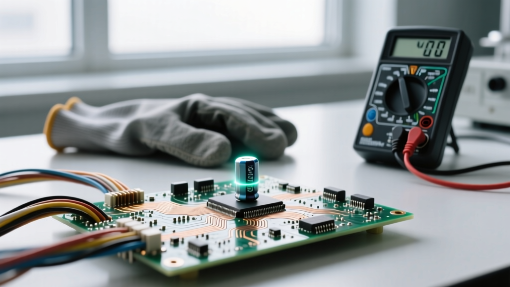
Lockout/Tagout (LOTO) procedures differ significantly between single-phase and three-phase systems. According to OSHA electrical safety standards, verifying a zero-energy state requires a rigorous "Live-Dead-Live" test using a properly rated digital multimeter (DMM). For three-phase systems, the testing matrix is vastly more complex. A CAT III 600V or CAT IV 600V rated meter is mandatory to handle the transient overvoltages inherent in industrial 3-phase grids.
Single-Phase 240V Verification (3-Point Test)
- Phase 1 (L1) to Phase 2 (L2)
- Phase 1 (L1) to Ground (G)
- Phase 2 (L2) to Ground (G)
Three-Phase 480V Verification (6-Point Test Minimum)
In a three-phase system, a single blown fuse or a failed contactor pole can leave one phase energized while the others read dead. Therefore, you must test every possible combination:
- Phase A to Phase B
- Phase B to Phase C
- Phase A to Phase C
- Phase A to Ground
- Phase B to Ground
- Phase C to Ground
Information Gain Insight: Never rely on panel-mounted indicator lights to verify a zero-energy state in a 3-phase system. Indicator lights can fail, or they may be wired to a separate control circuit that remains energized even when the main power disconnect is open. Always use a verified DMM directly on the busbars or load-side lugs.
The Danger of Motor Single-Phasing
Another critical safety difference involves how equipment handles faults. If a single-phase motor loses its power, it simply stops. If a three-phase motor loses one of its three phases—a condition known as "single-phasing"—the motor will often continue to run. However, it will draw massively disproportionate current on the remaining two phases to maintain torque.
This causes rapid thermal runaway in the motor windings. If the overload relays or phase-loss monitors are improperly sized or bypassed, the motor will overheat, melt its insulation, and ignite surrounding combustible materials. Troubleshooting a 3-phase motor that is humming, running hot, or emitting a burning smell requires immediate de-energization, as the chassis may become energized due to internal winding-to-ground insulation failure.
Grounding, Bonding, and Fault Current Paths
In single-phase residential systems, the grounding electrode system and the neutral are bonded at the main service disconnect. In large three-phase industrial facilities, you often deal with separately derived systems (like a 480V to 208V step-down transformer). The NEC requires the neutral and ground to be bonded only at the source of the separately derived system.
A common and dangerous mistake is bonding the neutral to the ground at a downstream 3-phase subpanel. This creates parallel neutral current paths on the equipment grounding conductors (EGC). If a fault occurs, the fault current divides unpredictably, potentially energizing the metal enclosures of connected machinery and rendering ground-fault protection devices (GFCIs/EFPEs) inoperative. For deep troubleshooting on grounding anomalies, referencing Fluke's guidelines on voltage and ground impedance testing is highly recommended to ensure the fault current path has low enough impedance to trip the breaker instantaneously.
Summary: Respect the Phase Shift
The difference between single-phase and three-phase electricity is not just a matter of adding more wires; it is a fundamental shift in electrical physics and hazard potential. Three-phase systems deliver relentless, zero-crossing-defying power that sustains arcs, complicates lockout verification, and hides lethal voltage anomalies like the high-leg delta. By adopting rigorous 6-point LOTO testing matrices, respecting NFPA 70E arc flash boundaries, and understanding the unique failure modes of 3-phase equipment, you ensure that your electrical work remains safe, compliant, and fundamentally sound.