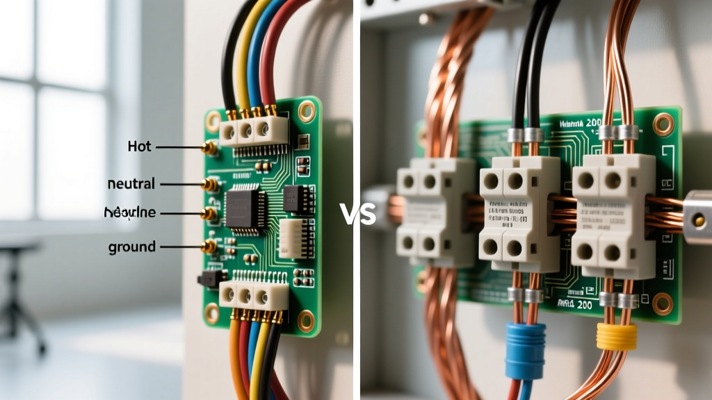

The Core Electrical Divide: Waveform and Code Definitions
When evaluating electrical infrastructure for residential, commercial, or industrial applications, the distinction between single phase versus 3 phase wiring extends far beyond basic physics. For electricians, engineers, and advanced DIYers, the true divergence lies in how the National Electrical Code (NEC) regulates installation, safety, conductor sizing, and panelboard configurations. While single-phase systems dominate residential construction, three-phase systems are the backbone of commercial and industrial power distribution due to their efficiency in running heavy inductive loads.
According to the NFPA 70 National Electrical Code, the rules governing branch circuits, feeders, and grounding shift significantly depending on the phase configuration. A standard residential split-phase system provides 120/240V using a single transformer secondary with a center-tapped neutral. Conversely, commercial three-phase systems typically operate as 120/208V Wye, 277/480V Wye, or 240V Delta configurations. Understanding these topological differences is critical for maintaining code compliance and preventing catastrophic equipment failure.
Multiwire Branch Circuits (MWBC) and Neutral Rules
One of the most heavily scrutinized areas in the NEC regarding phase configurations is the Multiwire Branch Circuit (MWBC), covered under NEC Article 210.4 and Article 215.4 for feeders. An MWBC consists of two or more ungrounded (hot) conductors and one grounded (neutral) conductor, which saves copper and reduces voltage drop.
In a single-phase 120/240V system, an MWBC utilizes two hot legs that are 180 degrees out of phase with each other. Because they are perfectly opposed, the neutral conductor only carries the unbalanced load (the mathematical difference between the two hot legs). If Leg A draws 12 amps and Leg B draws 10 amps, the neutral carries only 2 amps.
In a three-phase 120/208V Wye system, an MWBC utilizes three hot legs that are 120 degrees apart. The vector mathematics change drastically. If all three legs draw 10 amps of purely resistive linear load, the neutral current is theoretically zero. However, the NEC mandates strict handle-tie or common-trip breaker requirements (NEC 210.4(B)) for all MWBCs to ensure all ungrounded conductors are disconnected simultaneously during maintenance, preventing lethal shock hazards from back-fed neutrals.
The Triplen Harmonic Mandate (NEC 310.15)
The most dangerous code trap in three-phase wiring involves non-linear loads. Modern commercial buildings are filled with LED drivers, variable frequency drives (VFDs), and switch-mode power supplies. These devices generate 'triplen' harmonics (3rd, 9th, 15th). Unlike fundamental frequencies that cancel out in a Wye neutral, triplen harmonics are zero-sequence currents that add up arithmetically on the neutral bus.
'On a 3-phase, 4-wire wye circuit where the major portion of the load consists of nonlinear loads, the neutral conductor can carry more current than the phase conductors. Sizing the neutral at 100% of the phase conductor ampacity is often insufficient.' — Paraphrased from NEC Article 310.15 and industry power quality guidelines.
For detailed mitigation strategies, Fluke's guide on three-phase power quality highly recommends oversized neutrals or K-rated transformers. Under the NEC, if harmonic loads exceed specific thresholds, the neutral conductor in a 3-phase Wye system must be sized up to 200% of the phase conductors, a requirement that almost never applies to standard single-phase residential wiring.
High-Leg Delta Systems and NEC 408.3(E)
When discussing single phase versus 3 phase wiring, the High-Leg Delta (also known as the Red-Leg, Wild-Leg, or Stinger system) requires special attention. This 240V 3-phase Delta configuration features a center-tapped transformer on one of the windings to provide 120/240V single-phase power for lighting and receptacles, while maintaining 240V 3-phase for heavy motors.
The center tap creates a 'high leg' that measures approximately 208V to ground, rather than the standard 120V. Connecting a standard 120V single-phase load to this high leg will instantly destroy the equipment and create a severe fire hazard. To combat this, NEC 408.3(E) strictly mandates that the high-leg conductor must be durably identified by an orange outer finish at every point where the neutral is present. Furthermore, NEC 230.56 and 408.3(E) dictate specific phasing arrangements on busbars, typically requiring the high leg to be placed on the 'C' phase or the middle 'B' phase depending on the metering equipment and local utility standards.
Voltage Drop Formulas and Conductor Sizing
Voltage drop is a primary concern for long feeder runs, and the NEC addresses it in Informational Notes to Article 310.14 (formerly 310.15). While the NEC generally recommends a maximum of 3% voltage drop on branch circuits and 5% overall, the mathematical formulas used to calculate wire sizing differ by phase.
- Single-Phase Voltage Drop Formula: VD = (2 × K × I × D) / CM
- Three-Phase Voltage Drop Formula: VD = (√3 × K × I × D) / CM
The constant 2 in the single-phase formula accounts for the out-and-back distance of the current. In a balanced three-phase system, the constant is replaced by √3 (approximately 1.732). Because 1.732 is roughly 13.4% less than 2, a three-phase system inherently suffers less voltage drop for the exact same wire size, current, and distance. This mathematical advantage allows commercial facilities to use smaller, more cost-effective copper or aluminum conductors for heavy machinery feeders compared to an equivalent single-phase setup.
Grounding and Fault Current Considerations
Grounding and bonding, governed by NEC Article 250, also scale with phase complexity. Single-phase residential services typically utilize a simple grounding electrode system consisting of two ground rods or a single rod supplemented by a metal underground water pipe. The available fault current at a standard 200A residential panel rarely exceeds 10,000 to 22,000 amps.
Commercial three-phase services, however, frequently operate at 400A, 800A, or higher, with utility transformers capable of delivering 42,000 to 65,000+ amps of available fault current. This necessitates strict adherence to NEC 110.24 for available fault current documentation and requires panelboards with much higher AIC (Ampere Interrupting Capacity) ratings. Furthermore, three-phase industrial facilities often utilize structural steel and concrete-encased electrodes (Ufer grounds) as part of a robust grounding grid to safely dissipate massive fault energies and stabilize the system voltage to earth.
Code Comparison: Single Phase vs. 3 Phase Wiring
| Feature | Single-Phase (Split-Phase 120/240V) | Three-Phase (Wye 120/208V or 277/480V) |
|---|---|---|
| Primary NEC Articles | Art. 210, 215, 250, 310 | Art. 210, 215, 250, 310, 408, 430 |
| MWBC Neutral Sizing | Sized for maximum unbalanced linear load | Must account for triplen harmonics; often oversized up to 200% |
| Voltage Drop Constant | 2 (in VD formula) | √3 or 1.732 (in VD formula) |
| Motor Starting (Art. 430) | High starting torque stress; requires larger caps | Smooth, continuous rotating magnetic field; highly efficient |
| Typical Grounding Grid | 1-2 Ground Rods, Water Pipe Bond | Ufer Ground, Building Steel, Grounding Grid |
Decision Framework: When the Code Dictates an Upgrade
Choosing between single phase versus 3 phase wiring is rarely a matter of preference in commercial spaces; it is dictated by the load profile and the NEC. If your facility requires multiple motors exceeding 5 HP, heavy HVAC chillers, or industrial manufacturing equipment, the NEC motor overload and short-circuit protection rules (Article 430) heavily favor three-phase power. Three-phase motors do not require starting capacitors or centrifugal switches, drastically reducing maintenance and failure points.
For residential and light commercial projects, single-phase remains the undisputed standard due to utility availability and the simplicity of balancing standard 120V receptacle loads. However, as noted by electrical engineering foundations, attempting to run heavy 3-phase machinery on a single-phase supply using rotary or static phase converters introduces severe inefficiencies, voltage imbalances, and potential code violations regarding motor protection sizing. Always consult the local Authority Having Jurisdiction (AHJ) and perform a comprehensive load calculation per NEC Article 220 before finalizing your system topology.