
The Skill-Building Path to SD Card Data Logging
Integrating an SD card module into a microcontroller project is a rite of passage for electronics enthusiasts and embedded engineers alike. Whether you are building an environmental data logger, a GPS tracker, or a DIY oscilloscope, local non-volatile storage is essential. However, the journey from inserting a MicroSD card to successfully logging CSV data is fraught with hidden hardware traps, voltage mismatches, and filesystem bottlenecks.
This guide is structured as a skill-building path. We will progress from beginner hardware selection and the infamous 3.3V logic trap, through intermediate SPI wiring and power delivery optimization, and finally to advanced filesystem formatting and SPI clock debugging. By the end of this guide, you will possess the domain expertise to reliably deploy SD storage in any embedded environment.
Phase 1: Hardware Selection and the 3.3V Logic Trap (Beginner)
The most common point of failure for beginners is destroying the MicroSD card's internal controller due to logic level mismatches. Standard SD cards operate strictly at 3.3V. However, popular beginner microcontrollers like the Arduino Uno (ATmega328P) output 5V on their digital pins.
The 'Blue Module' vs. Dedicated Breakouts
If you purchase a generic LC Studio 'blue' SD card module, you will notice it includes an onboard AMS1117 3.3V LDO voltage regulator and a resistor network for logic level shifting. While this module works for basic 5V Arduino projects, the resistor-based level shifting is notoriously unreliable at higher SPI clock speeds, leading to corrupted data. Furthermore, the AMS1117 LDO on cheap clone boards often lacks adequate decoupling capacitors, causing brownouts during write operations.
For a robust skill-building foundation, we recommend investing in a dedicated breakout board like the Adafruit MicroSD Breakout Board. These modules utilize proper MOSFET-based logic level shifting (like the BSS138) or dedicated ICs like the CD4050, ensuring clean signal edges and protecting your 3.3V SD card from 5V overvoltage damage.
Phase 2: Mastering the SPI Wiring Matrix (Intermediate)
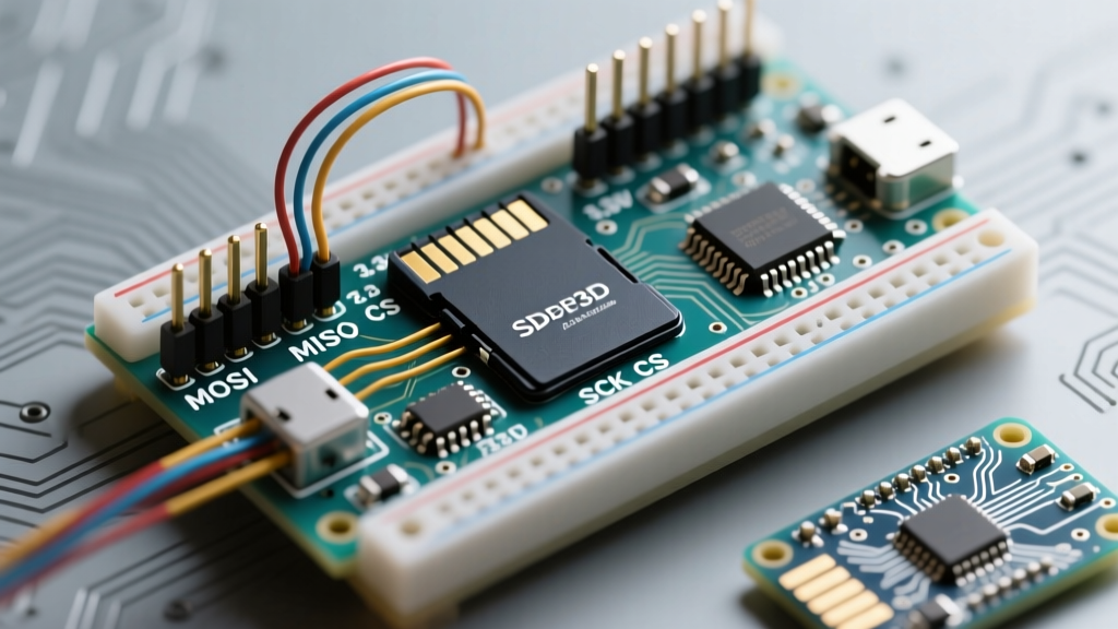
Most hobbyist SD card modules communicate via the Serial Peripheral Interface (SPI). Unlike I2C, SPI does not have a standardized hardware address; instead, it relies on a Chip Select (CS) pin to initiate communication with a specific peripheral. Below is the definitive wiring matrix for connecting a standard MicroSD module to popular microcontroller architectures.
| SD Module Pin | Function | Arduino Uno / Nano | Arduino Mega 2560 | ESP32 (Standard SPI) |
|---|---|---|---|---|
| VCC | Power (5V or 3.3V depending on module LDO) | 5V | 5V | 3.3V (or 5V if LDO equipped) |
| GND | Ground | GND | GND | GND |
| MISO | Master In, Slave Out (Data to MCU) | Pin 12 | Pin 50 | GPIO 19 |
| MOSI | Master Out, Slave In (Data to SD) | Pin 11 | Pin 51 | GPIO 23 |
| SCK / CLK | Serial Clock | Pin 13 | Pin 52 | GPIO 18 |
| CS / SS | Chip Select (Any GPIO, usually 10 or 4) | Pin 10 | Pin 53 | GPIO 5 |
Crucial Note for ESP32 Users: The ESP32 operates natively at 3.3V. Never use a 5V level-shifting module with an ESP32, as the module's LDO will step the 3.3V logic down to roughly 2.0V, which falls below the SD card's logic high threshold. Wire 3.3V ESP32 GPIOs directly to raw MicroSD breakout pins.
Phase 3: Power Delivery and Decoupling (Intermediate)
A frequently overlooked aspect of SD card module integration is power delivery. During a write burst, an SD card can draw transient current spikes exceeding 200mA. If your microcontroller's 3.3V rail is shared with sensors or lacks sufficient capacitance, the voltage will sag, causing the SD card's internal state machine to crash and corrupting the File Allocation Table (FAT).
The Decoupling Fix
To ensure enterprise-grade reliability in your DIY data loggers, you must stabilize the power rail. Solder a 100µF electrolytic capacitor and a 0.1µF ceramic capacitor directly across the VCC and GND pins on the SD module's PCB. This local energy reservoir absorbs the high-frequency transient spikes during block writes, preventing the dreaded 'card disconnected' errors that plague long-term logging projects.
Phase 4: The Filesystem Bottleneck (Advanced)
The physical wiring is only half the battle. The logical formatting of the MicroSD card dictates whether your microcontroller can actually mount the drive. The standard Arduino SD library only supports FAT16 and FAT32 filesystems. It will completely fail to initialize SDXC cards formatted in exFAT.
Formatting for Embedded Success
- Avoid OS Native Formatters: Windows and macOS often format large cards with non-standard cluster sizes or hidden EFI partitions that confuse microcontroller bootloaders.
- Use the Official Tool: Download the 'SD Memory Card Formatter' from the official SD Association.
- Cluster Size Matters: For cards 32GB and under, format to FAT32. If given the option, force an Allocation Unit Size (Cluster Size) of 32KB. This aligns perfectly with the internal erase block sizes of most NAND flash memory, reducing write amplification and speeding up your microcontroller's file operations.
Phase 5: Troubleshooting 'CardInfo Fail' and SPI Clocks (Expert)
If you have verified your wiring, confirmed your 3.3V logic levels, and formatted to FAT32, but the standard CardInfo.ino sketch still returns 'initialization failed', you are likely facing an SPI timing or signal integrity issue.
Three Expert Debugging Steps
- Pull-Up Resistors: The MISO line is high-impedance when the SD card is deselected. If you have multiple SPI devices on the same bus (like an NRF24L01 radio and an SD module), add a 10kΩ pull-up resistor between MISO and 3.3V to prevent floating states from triggering phantom interrupts.
- Lower the SPI Clock Divider: Cheap SD modules with long, unshielded jumper wires act as antennas, introducing capacitance that ruins high-frequency SPI edges. In your code, initialize the card with a slower clock speed. In the standard SD library, use
SD.begin(chipSelect, SPI_HALF_SPEED)to drop the clock from 8MHz to 4MHz, vastly improving signal integrity over breadboards. - Upgrade to SdFat: The native Arduino SD library is a simplified wrapper that lacks advanced error handling. Migrate to Bill Greiman's SdFat library. SdFat supports exFAT, SDIO, and provides verbose error codes via
sd.initErrorHalt(), pinpointing exactly which stage of the SPI handshake is failing.
Beyond SPI: Knowing When to Upgrade to SDIO
Pro-Tip: SPI is inherently limited. Because it uses a single data line (MISO) for reading, maximum theoretical throughput on an Arduino is roughly 1-2 MB/s. If your skill-building path leads you toward high-speed data acquisition—such as logging uncompressed WAV audio or capturing high-sample-rate oscilloscope data—you must abandon SPI modules and design a custom PCB utilizing the SDIO (Secure Digital Input Output) 4-bit bus interface, which can push transfer rates past 25 MB/s on capable 32-bit ARM microcontrollers.
Mastering the SD card module is about understanding the intersection of physical electronics, signal integrity, and logical filesystems. By respecting the 3.3V logic threshold, stabilizing your power delivery, and utilizing professional formatting tools, you transform a frustrating hobbyist component into a bulletproof embedded storage solution.