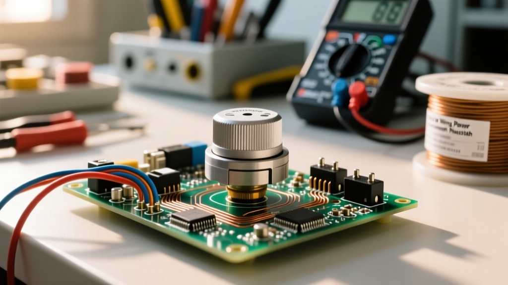

The Hidden Dangers of High-Wattage Variable Resistors
When most DIYers and hobbyists think about wiring a potentiometer, they envision low-voltage, low-current applications like Arduino sensor inputs or audio volume knobs. In those milliamp signal circuits, a wiring mistake usually results in nothing more than a noisy signal or a dead channel. However, in the realm of general electrical wiring, industrial motor control, and high-power lighting, potentiometers take on a vastly different and far more dangerous form: the wirewound power rheostat.
Power potentiometers—typically rated from 25W to over 1000W—are used to control heavy loads such as DC motor speeds, industrial heating elements, and high-bay lighting arrays. When wiring a potentiometer in these high-current environments, the stakes change dramatically. A loose connection can cause localized arcing, leading to fires. An improperly configured wiper can cause thermal runaway, destroying downstream components or causing lethal electric shocks. Adhering to stringent safety best practices is not just a recommendation; it is an absolute necessity to comply with electrical codes and prevent catastrophic equipment failure.
Carbon Track vs. Wirewound: A Thermal Safety Comparison
Before making any physical connections, you must select the correct component for the electrical load. Using a standard carbon-track potentiometer in a high-power circuit is a severe fire hazard. Carbon tracks cannot dissipate the heat generated by multi-amp currents, leading to rapid thermal degradation and literal combustion of the resistive element.
| Feature | Carbon / Cermet Track | Wirewound (Power Rheostat) |
|---|---|---|
| Max Wattage | 0.5W to 2W | 25W to 1000W+ |
| Temp Coefficient | High (Prone to drift) | Low (Stable under heat) |
| Primary Failure Mode | Thermal cracking, combustion | Wire oxidation, wiper lift |
| Max Working Voltage | ~250V AC/DC | Up to 1000V+ (Model dependent) |
| Safety Application | Signal isolation only | Direct load control (with derating) |
For any circuit drawing more than 100mA of continuous current, you must use a wirewound potentiometer, such as the Ohmite 280 Series or Vishay 534 Series. These feature a resistive wire wrapped around a ceramic or fiberglass core, specifically designed to handle extreme thermal loads.
The Wiper Failsafe: Preventing Runaway Current
The most critical safety concept when wiring a potentiometer as a variable resistor (rheostat) is the 'Wiper Failsafe Configuration'. A standard potentiometer has three terminals: Terminal 1 (Clockwise), Terminal 2 (Wiper), and Terminal 3 (Counter-Clockwise).
If you wire your circuit using only Terminal 1 and the Wiper (Terminal 2), you create a severe hazard. Over time, mechanical vibration or thermal cycling can cause the wiper to momentarily lose physical contact with the resistive wire. If this happens in a 2-terminal configuration, the resistance instantly spikes to infinity (an open circuit). In a motor control or heating circuit, an open circuit can cause voltage spikes, destroy solid-state drivers, or cause the load to behave unpredictably.
The Safe Wiring Protocol
To prevent this, you must wire the potentiometer using a failsafe jumper. Connect your incoming wire to Terminal 1. Then, install a jumper wire between Terminal 2 (Wiper) and Terminal 3. Connect your outgoing load wire to Terminal 3.
- Normal Operation: Current flows through the wiper, taking the path of least resistance.
- Failsafe Operation: If the wiper lifts off the track, the current seamlessly continues through the jumper wire into the remaining resistive track. Instead of an open circuit, the resistance simply defaults to the maximum value (safely reducing power to the load rather than cutting it entirely or causing a voltage spike).
Expert Insight: Never rely on the wiper alone to carry high current in safety-critical circuits. Always tie the wiper to the unused end terminal to ensure the circuit remains closed even during mechanical failure.
Mechanical and Thermal Wiring Protocols
High-wattage potentiometers generate immense heat. The physical wiring and mounting techniques must account for thermal expansion and contraction.
Terminal Lug Crimping and Torque
Never wrap bare wire around the screw terminals of a power potentiometer. The repeated heating and cooling cycles will cause the wire to expand and contract, eventually loosening the connection. A loose connection increases contact resistance, which generates even more heat, creating a destructive feedback loop that ends in a melted terminal block or fire.
- Strip your high-temperature wire (e.g., 14 AWG silicone jacketed wire for 50W+ loads).
- Crimp a high-quality ring terminal (such as a Panduit P18-10R) using a calibrated ratcheting crimper.
- Secure the ring terminal to the potentiometer screw. Use a torque screwdriver set to the manufacturer's specification (typically around 0.5 Nm to 0.7 Nm for standard 6-32 brass screws). Over-torquing will strip the soft brass threads, while under-torquing will lead to arcing.
Heat Sink Mounting and Derating
A 50W potentiometer is only rated for 50W if it is mounted to a massive, infinite heat sink. In real-world enclosures, ambient temperatures rise quickly. According to standard manufacturer derating curves, a potentiometer's wattage capacity drops linearly once ambient temperatures exceed 50°C, reaching zero capacity at 150°C. Always apply a thin layer of high-quality thermal interface material (like Arctic Silver or standard silicone thermal paste) between the potentiometer's metal bracket and the chassis heat sink to ensure optimal thermal transfer.
Isolation and Shock Prevention in AC/DC Circuits
When wiring a potentiometer directly into AC mains or high-voltage DC bus lines (such as 120V/240V AC or 300V+ DC motor drives), galvanic isolation is a life-saving requirement. The metal shaft of a standard wirewound potentiometer is often electrically connected to the internal resistive track via the wiper and the mounting hardware.
If an internal dielectric breakdown occurs, the metal shaft can become energized at line voltage. To prevent lethal shock hazards, the National Fire Protection Association (NFPA 70) and general industrial safety standards dictate the use of isolation techniques:
- Plastic Shafts: Always specify potentiometers with molded nylon or phenolic shafts for high-voltage applications.
- Isolation Transformers: When testing or tuning high-power AC circuits, power the system through an isolation transformer to prevent ground faults from passing through the user.
- Optocouplers and Signal Isolators: In modern industrial wiring, it is vastly safer to use a low-voltage (5V-10V) potentiometer to send a signal to an optocoupler or PLC analog input, which then controls a high-power solid-state relay (SSR) or variable frequency drive (VFD). This completely removes high voltage from the operator's control panel.
Troubleshooting Common Failure Modes
Even with perfect installation, power potentiometers are subject to harsh electrical environments. According to diagnostic guidelines from Fluke Electrical Safety and component manufacturers like Ohmite Manufacturing, technicians should monitor for the following specific failure modes:
1. Hot Spotting and Track Burnout
If a potentiometer is frequently left at a very low resistance setting (e.g., 5% of total travel) while passing high current, the small segment of wire carrying the load will overheat, creating a 'hot spot'. This degrades the wire's enamel coating, leading to shorted turns. To prevent this, design your circuit so the normal operating range utilizes the middle 60% of the potentiometer's travel.
2. Wiper Oxidation and Arcing
In DC motor control circuits, the inductive kickback from the motor can cause micro-arcing between the wiper and the wirewound track. This arcing pits the wire and oxidizes the wiper contact, resulting in erratic resistance and audible 'crackling' in audio circuits or 'stuttering' in motor speeds. Installing a snubber circuit (a capacitor and resistor in series) across the potentiometer terminals will absorb these inductive spikes and dramatically extend the component's lifespan.
3. Shaft Grounding Loops
If the potentiometer is mounted to a grounded metal panel, and the internal track develops a fault to the chassis, a ground loop can form, introducing 60Hz hum into sensitive control circuits or tripping GFCI breakers. Always use insulated mounting washers and shoulder bushings when installing power rheostats into grounded metal enclosures.
By treating the potentiometer not just as a simple knob, but as a high-power thermal and electrical component, you ensure the safety, longevity, and reliability of your electrical wiring projects. Always verify wattage ratings, enforce wiper failsafes, and prioritize galvanic isolation when dealing with hazardous voltages.