
The Evolution of the 40-Pin Header: Pi 4 vs. Pi 5
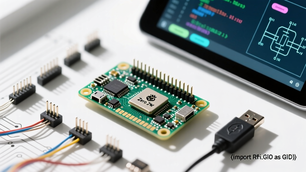
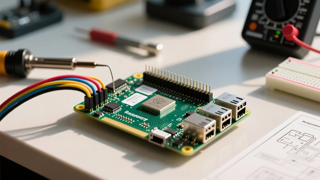
The 40-pin GPIO header is the central nervous system of any hardware project built on a single-board computer. While the physical layout of the Raspberry Pi pins has remained remarkably consistent since the Model B+ days, the underlying silicon architecture has undergone a massive shift. Understanding these differences is critical for safe setup and configuration, especially when migrating code or hardware designs between generations.
On the Raspberry Pi 4 Model B, the GPIO matrix is controlled directly by the BCM2711 SoC. However, the Raspberry Pi 5 introduces the RP1 chip, a custom-designed southbridge that offloads peripheral management (including the 40-pin header, USB, and Ethernet) from the main BCM2717 processor. This architectural shift means that while the physical pinout remains backward compatible, the memory-mapped addresses and low-level software configurations have changed. Modern setup guides must account for this transition, particularly when dealing with bare-metal programming or custom device tree overlays.
Anatomy of the Raspberry Pi Pins Matrix
Before wiring any sensors, relays, or microcontrollers, you must understand the distinct zones of the 40-pin header. A common beginner mistake is treating all pins as generic I/O, which can lead to catastrophic short circuits. According to the Raspberry Pi Official GPIO Documentation, the header is divided into specific functional rails.
| Category | Pin Count | Physical Pins | Configuration Notes |
|---|---|---|---|
| 5V Power | 2 | 2, 4 | Directly tied to USB-C input. Max current draw depends on your power supply (typically up to 3A-5A total system). |
| 3.3V Power | 2 | 1, 17 | Regulated output. Strictly limited to ~50mA total across all connected peripherals on Pi 4. |
| Ground (GND) | 8 | 6, 9, 14, 20, 25, 30, 34, 39 | Essential for completing circuits. Always use the shortest path to GND to minimize inductive noise. |
| Standard GPIO | 26 | Various | 3.3V logic level. Can be configured as inputs, outputs, or alternate functions via software. |
| Specialized Buses | N/A | I2C (3,5), SPI (19,21,23), UART (8,10) | Require specific software enablement via raspi-config or config.txt. |
Software Configuration: The Shift to libgpiod
If you are setting up a new Raspberry Pi running OS Bookworm or later, you must abandon the legacy RPi.GPIO Python library. It is no longer actively maintained and lacks full support for the Pi 5's RP1 architecture. The modern, kernel-compliant standard for configuring and manipulating Raspberry Pi pins is libgpiod (and its Python wrapper, gpiod), alongside the beginner-friendly gpiozero library.
Enabling Hardware Interfaces
By default, specialized pins are configured as standard GPIO inputs to prevent conflicts. To configure them for their alternate functions, you must edit the boot configuration. On modern Raspberry Pi OS, this file is located at /boot/firmware/config.txt.
- I2C Setup: Add
dtparam=i2c_arm=on. This enables I2C1 on pins 3 (SDA) and 5 (SCL). - SPI Setup: Add
dtparam=spi=on. This activates the SPI0 bus (MOSI on 19, MISO on 21, SCLK on 23). - UART Setup: Add
enable_uart=1. Note that on Pi 3, 4, and 5, you must also disable the serial console inraspi-configto free up pins 8 (TX) and 10 (RX) for external microcontrollers like Arduino or ESP32.
Command-Line Pin Inspection
Before writing a single line of code, use the libgpiod command-line tools to verify your pin states. Running gpioinfo in the terminal will output a comprehensive list of all available lines, their current kernel mappings, and whether they are actively claimed by another process (like the I2C daemon). This is an invaluable troubleshooting step when a sensor fails to respond.
Hardware Setup: Current Limits and Safe Wiring
The most frequent cause of permanent hardware failure in SBC projects is ignoring the electrical limits of the Raspberry Pi pins. The GPIO matrix operates at 3.3V logic. It is not 5V tolerant. Injecting 5V into any GPIO pin will instantly destroy the internal ESD protection diodes and fry the SoC (or the RP1 chip on Pi 5).
| Parameter | Absolute Maximum | Recommended Safe Limit | Engineering Context |
|---|---|---|---|
| Single GPIO Pin Output | 16 mA | 3 mA - 5 mA | Sufficient to drive an LED with a resistor or the base of a switching transistor. |
| Total GPIO Bank Current | 50 mA | < 40 mA | The sum of all current sourced/sunk by all GPIO pins combined must not exceed this. |
| 3.3V Rail Total Draw | 50 mA (Pi 4) | < 30 mA | Pi 5 features an upgraded PMIC, but external sensors should still use 5V rail with logic level shifters when possible. |
Designing Safe Output Circuits
Never connect high-current loads (motors, solenoids, high-power relays) directly to the Raspberry Pi pins. Instead, use a logic-level N-channel MOSFET (like the IRLZ44N) or an optocoupler (like the PC817) to isolate the Pi's delicate 3.3V logic from the high-current 5V or 12V load circuits. When driving inductive loads like relays, you must place a flyback diode (e.g., 1N4007) in reverse parallel across the relay coil. Failing to do so will result in back-EMF voltage spikes that will arc back through the transistor and destroy the GPIO pin.
Expert Warning: Backpowering the Raspberry Pi via the 5V GPIO pins (Pins 2 or 4) bypasses the onboard USB-C Power Delivery negotiation and protection circuitry. If your external 5V supply experiences a voltage spike exceeding 5.25V, it can permanently damage the board's PMIC and downstream components. Always power the board via the official USB-C port for setup and configuration.
Real-World Configuration: Setting Up an I2C Sensor Bus
Let us apply this knowledge to a common scenario: configuring an I2C environmental sensor (like the BME280) on the primary I2C bus. The physical setup requires connecting Pin 1 (3.3V), Pin 6 (GND), Pin 3 (SDA), and Pin 5 (SCL).
The Pull-Up Resistor Factor
I2C requires pull-up resistors on the SDA and SCL lines. The Raspberry Pi includes onboard 1.8kΩ pull-up resistors tied to the 3.3V rail for I2C1. While 1.8kΩ is quite strong (low resistance), it works well for short wire runs (under 30cm) and a single device. However, if you are daisy-chaining multiple I2C devices, the bus capacitance increases. According to the Pinout.xyz I2C specifications, excessive capacitance combined with strong pull-ups will degrade the square wave signal into a sawtooth pattern, causing data corruption. If you encounter I2C timeouts on a multi-device bus, disable the onboard pull-ups via device tree overlays and add external 4.7kΩ pull-up resistors to your breadboard.
Software Verification Steps
- Enable I2C via
sudo raspi-config(Interface Options > I2C). - Reboot the system to load the
i2c-devkernel module. - Install the diagnostic tools:
sudo apt install i2c-tools. - Run
i2cdetect -y 1. A properly configured sensor will appear as a hexadecimal address (e.g.,76or77for the BME280) in the resulting grid.
Summary Checklist for Pin Configuration
Before applying power to your next project, run through this mental checklist to ensure your Raspberry Pi pins are configured for success:
- Voltage Verification: Have I confirmed that all sensors and microcontrollers communicating with the GPIO are strictly 3.3V logic, or have I implemented a bidirectional logic level shifter (like the BSS138)?
- Current Budgeting: Does my total GPIO current draw remain under the 40mA safe threshold?
- Software State: Have I verified pin assignments using
gpioinfoto ensure the kernel isn't holding the pin for an active overlay? - Protection: Are flyback diodes installed on all relays, and are current-limiting resistors present on all LEDs?
By respecting the electrical boundaries and leveraging modern software tools like libgpiod, you transform the 40-pin header from a fragile bottleneck into a robust, industrial-grade interface capable of driving complex smart home and robotics architectures.