
The Legacy 26-Pin Header: Why It Still Matters
While modern single-board computers boast 40-pin headers and integrated AI accelerators, the original Raspberry Pi 1 Model B remains a staple in retro kiosks, low-power IoT nodes, and vintage maker projects. Understanding the original raspberry pi b gpio pinout is essential for maintaining legacy hardware or salvaging components from early 2012-era kits. Unlike the standardized 40-pin layout introduced with the Pi 1 Model B+ and subsequent generations, the original Model B features a 26-pin header that harbors a few critical hardware quirks. This guide provides a comprehensive, electrically accurate breakdown of the 26-pin layout, the vital differences between board revisions, and safe interfacing techniques for the BCM2835 SoC.
The Critical Divide: Revision 1 vs. Revision 2
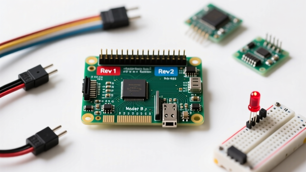
The most common pitfall when working with the Raspberry Pi B GPIO pinout is assuming all 26-pin boards are identical. They are not. The Raspberry Pi Foundation silently updated the board layout in late 2012, creating a split that still causes I2C communication failures and GPIO mapping errors today.
Identifying Your Board Revision
To determine your board revision, inspect the physical PCB or query the SoC via the terminal. Early Revision 1 boards (manufactured before September 2012) typically feature 256MB of RAM, lack mounting holes, and have a board ID of 0002 or 0003. Revision 2 boards introduced 512MB of RAM, added mounting holes, and carry IDs like 0004, 0005, or 0006. You can verify this by running cat /proc/cpuinfo in the terminal and checking the 'Revision' field.
The Pin 13 and I2C Anomaly
The physical pin locations on the header remained the same, but the underlying BCM2835 routing changed drastically:
- I2C Bus Swap: On Rev 1, pins 3 and 5 are connected to I2C Bus 0 (GPIO 0 and GPIO 1). On Rev 2, these pins were rerouted to I2C Bus 1 (GPIO 2 and GPIO 3). If you are writing bare-metal C code or using legacy Python scripts hardcoded to
i2c-0, your sensors will fail to initialize on a Rev 2 board. - The Pin 13 Trap: Physical Pin 13 is mapped to GPIO 21 on Rev 1 boards, but it was changed to GPIO 27 on Rev 2 boards. Always use the Broadcom (BCM) numbering system in your code and verify your hardware revision to avoid toggling the wrong physical pin.
According to the definitive hardware archives at eLinux RPi Low-level Peripherals, these changes were made to align the primary I2C bus with the standard P1 header conventions used across the broader embedded industry.
Comprehensive Raspberry Pi B GPIO Pinout Table
Below is the complete mapping for the 26-pin header. This table assumes the standard BCM (Broadcom) numbering scheme, which is the recommended standard for modern Python libraries like gpiozero. For an interactive visual representation, makers frequently reference the gold-standard database at Pinout.xyz.
| Physical Pin | Function / Label | BCM GPIO (Rev 2) | Notes |
|---|---|---|---|
| 1 | 3.3V Power | - | Max continuous draw ~50mA |
| 2 | 5V Power | - | Direct from USB/Polyfuse |
| 3 | SDA1 (I2C) | GPIO 2 | Requires 1.8k pull-up resistors |
| 4 | 5V Power | - | - |
| 5 | SCL1 (I2C) | GPIO 3 | Requires 1.8k pull-up resistors |
| 6 | Ground | - | - |
| 7 | GPCLK0 | GPIO 4 | General purpose I/O |
| 8 | TXD (UART) | GPIO 14 | Serial console transmit |
| 9 | Ground | - | - |
| 10 | RXD (UART) | GPIO 15 | Serial console receive |
| 11 | General I/O | GPIO 17 | - |
| 12 | PWM0 | GPIO 18 | Hardware PWM capable |
| 13 | General I/O | GPIO 27 | GPIO 21 on Rev 1 boards! |
| 14 | Ground | - | - |
| 15 | General I/O | GPIO 22 | - |
| 16 | General I/O | GPIO 23 | - |
| 17 | 3.3V Power | - | - |
| 18 | General I/O | GPIO 24 | - |
| 19 | SPI0 MOSI | GPIO 10 | Master Out Slave In |
| 20 | Ground | - | - |
| 21 | SPI0 MISO | GPIO 9 | Master In Slave Out |
| 22 | General I/O | GPIO 25 | - |
| 23 | SPI0 SCLK | GPIO 11 | Serial Clock |
| 24 | SPI0 CE0 | GPIO 8 | Chip Enable 0 |
| 25 | Ground | - | - |
| 26 | SPI0 CE1 | GPIO 7 | Chip Enable 1 |
Hardware Safety: Interfacing 5V Logic with the BCM2835
The BCM2835 SoC operates strictly on 3.3V logic. Unlike the ATmega328P found in the Arduino Uno, which tolerates 5V natively, feeding a 5V signal into any GPIO pin on the Raspberry Pi B will force current backward through the SoC's internal protection diodes. This will permanently destroy the pin, and if the current exceeds the diode's thermal limits, it will fry the entire BCM2835 chip and potentially the onboard LAN/USB controller.
Current Limits and Internal Pull Resistors
Each GPIO pin can safely source or sink up to 16mA. However, the BCM2835 datasheet specifies a strict total bank limit of 50mA across all GPIO pins combined. If you are driving multiple LEDs or optocouplers, you must use external transistors (like the 2N2222) or ULN2803 Darlington arrays. Additionally, the SoC features internal pull-up and pull-down resistors ranging from 50kΩ to 65kΩ, which can be configured via software to prevent floating inputs when wiring mechanical switches.
Implementing a Logic Level Shifter
When connecting 5V Arduino sensors (like the HC-SR04 ultrasonic module) to the Pi's 3.3V RX pins, you must step down the voltage. While a simple resistor voltage divider (e.g., a 2kΩ and 3.3kΩ resistor pair) works for low-speed signals, it degrades signal integrity on high-speed buses like SPI or I2C. For bidirectional or high-speed communication, use a dedicated logic level shifter IC like the TI SN74LVC245AN or a MOSFET-based bidirectional shifter (like the BSS138 breakout boards commonly sold by SparkFun and Adafruit).
Step-by-Step Tutorial: Safe LED Control via Python
Let's put the pinout into practice. We will wire an LED to Physical Pin 11 (BCM GPIO 17) and control it using the modern gpiozero library. Always use a current-limiting resistor (220Ω to 330Ω) to prevent drawing more than the 16mA limit.
Wiring the Circuit
- Connect a jumper wire from Physical Pin 11 (GPIO 17) to the anode (long leg) of the LED.
- Connect the cathode (short leg) of the LED to a 220Ω resistor.
- Connect the other end of the resistor to Physical Pin 9 (Ground).
Python Implementation
Open your terminal and ensure gpiozero is installed (sudo apt install python3-gpiozero). Create a file named blink.py and insert the following code:
from gpiozero import LED
from time import sleep

# Initialize GPIO 17 (Physical Pin 11)
red_led = LED(17)

try:
    while True:
        red_led.on()
        sleep(1)
        red_led.off()
        sleep(1)
except KeyboardInterrupt:
    # Safely clean up and turn off the LED on exit
    red_led.off()
    print('Program terminated safely.')
Run the script using python3 blink.py. The gpiozero library automatically handles the BCM mapping and sets the pin direction to output, eliminating the manual setup boilerplate required by the older RPi.GPIO library.
Troubleshooting Common GPIO Failures
If your Raspberry Pi B GPIO pinout mappings seem correct but the pins remain unresponsive, follow this diagnostic framework:
- The 3.3V Rail Check: Use a multimeter to measure the voltage between Physical Pin 1 (3.3V) and Physical Pin 6 (GND). If you read significantly less than 3.3V (or 0V), the onboard LDO regulator has likely failed due to a previous 5V short circuit on a GPIO pin. The SoC may still boot via the 5V rail, but all GPIO logic will be dead.
- UART Conflicts: By default, Pins 8 and 10 (GPIO 14/15) are assigned to the serial console. If you are trying to use them for standard GPIO or external serial devices, you must disable the serial console in
sudo raspi-configunder 'Interface Options' -> 'Serial Port'. - I2C Pull-ups: If your I2C sensors on Pins 3 and 5 are returning 'device not found' errors, verify that your breakout board includes physical pull-up resistors. The BCM2835's internal pull-ups are often too weak (50kΩ) for reliable I2C communication over longer wires; external 4.7kΩ resistors tied to the 3.3V rail are highly recommended.
Mastering the quirks of the original 26-pin layout ensures your legacy projects remain robust, safe, and fully operational for years to come.