
Beyond the Hardware: Mapping the Raspberry Pi 3 Pinout in Software
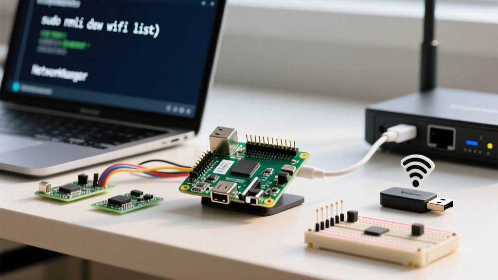
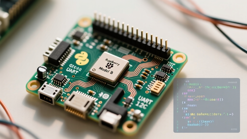
When engineers and hobbyists first approach the Raspberry Pi 3 pinout, the immediate focus is usually on the physical 40-pin header diagram. However, connecting a wire to physical pin 11 (BCM 17) is only ten percent of the battle. The true complexity of the Raspberry Pi 3 Model B and B+ lies in how the underlying BCM2837 SoC maps these physical pins to software interfaces, device tree overlays, and peripheral buses. Unlike simpler microcontrollers, the Raspberry Pi runs a full Linux kernel, meaning GPIO states, serial consoles, and I2C buses must be explicitly claimed, configured, and managed via software.
In this software walkthrough, we will bypass basic LED-blinking tutorials and dive deep into the operating system-level configurations required to make the Raspberry Pi 3 pinout function reliably in production environments. We will cover the notorious Pi 3 UART bottleneck, I2C bus configuration, and the modern Python GPIO ecosystem.
The UART Bottleneck: Resolving Pi 3 Serial Console Conflicts
The most infamous software quirk specific to the Raspberry Pi 3 pinout involves the Universal Asynchronous Receiver-Transmitter (UART) pins. On physical pins 8 (TXD) and 10 (RXD), developers expect to find a stable, hardware-backed serial console. On the Pi 1 and Pi 2, this was mapped to ttyAMA0 (the PL011 hardware UART).
However, the Pi 3 introduced an onboard Bluetooth module. To support this, the Raspberry Pi Foundation routed the high-performance PL011 UART to the Bluetooth chip, leaving the GPIO header's serial pins mapped to ttyS0, the 'mini-UART'.
The Mini-UART Core Clock Problem
The mini-UART lacks a dedicated baud-rate clock. Instead, its baud rate is tied to the SoC's core clock frequency. If your Pi 3's CPU load changes and the core clock scales dynamically, the baud rate drifts, resulting in corrupted serial data and dropped connections. If you are using the Raspberry Pi 3 pinout to communicate with a GPS module, a 3D printer mainboard, or an industrial PLC via RS-232, this clock drift will cause silent failures.
Software Fix: Device Tree Overlays in config.txt
To reclaim the stable PL011 UART for your GPIO header pins, you must disable the Bluetooth module via a device tree overlay. Open your boot configuration file (located at /boot/config.txt on older OS versions, or /boot/firmware/config.txt on Raspberry Pi OS Bookworm) and append the following lines:
# Disable Bluetooth to free up ttyAMA0 for GPIO pins 8 and 10
dtoverlay=disable-bt

# Enable the UART on the GPIO header
enable_uart=1
After rebooting, the PL011 UART is restored to the GPIO header. You can verify this in the terminal by checking the serial device mapping:
ls -l /dev/serial*You should see /dev/serial0 symlinked to ttyAMA0, guaranteeing a stable baud rate for your serial peripherals.
Configuring I2C and SPI via raspi-config and Python
The Raspberry Pi 3 pinout exposes the I2C1 bus on physical pins 3 (SDA) and 5 (SCL), and the SPI0 bus on pins 19 (MOSI), 21 (MISO), 23 (SCLK), and 24 (CE0). By default, the Linux kernel does not load the drivers for these buses to save memory and prevent pin conflicts.
Enabling the Buses
The safest software method to enable these interfaces is via the raspi-config tool:
- Open the terminal and type
sudo raspi-config. - Navigate to Interface Options.
- Select I2C and choose Yes to enable the ARM I2C interface.
- Repeat the process for SPI.
Under the hood, this tool modifies the config.txt file by adding dtparam=i2c_arm=on and dtparam=spi=on.
Verifying I2C and Handling Pull-Up Resistors
A critical hardware-software intersection on the Pi 3 is the I2C pull-up resistors. The Pi 3 board features onboard 1.8kΩ pull-up resistors tied to 3.3V for the I2C1 bus. In your software, you must never enable internal software pull-ups for BCM 2 and BCM 3, as this can cause bus contention.
Install the I2C tools and the Python SMBus library:
sudo apt update
sudo apt install i2c-tools python3-smbus
Scan the bus to verify software communication with your peripherals:
i2cdetect -y 1This command queries the I2C1 bus (the -y 1 flag bypasses the interactive confirmation prompt). A grid will appear showing the hexadecimal addresses of all responding devices.
Python GPIO Walkthrough: The Shift to gpiozero and lgpio
For years, the RPi.GPIO library was the undisputed king of Raspberry Pi software pin control. However, with the release of Raspberry Pi OS Bookworm and the shift to Linux Kernel 6.x, the legacy sysfs GPIO interface was deprecated. RPi.GPIO now frequently throws RuntimeError errors on modern Pi 3 setups.
The official recommendation is to use the gpiozero library, which abstracts the underlying hardware and utilizes the modern lgpio C library backend for character-device GPIO access.
Software Pull-Up/Pull-Down Configuration
When wiring a mechanical button to the Raspberry Pi 3 pinout, floating pins can cause phantom interrupts. While physical resistors work, configuring software pull-ups is more efficient. Here is a robust implementation using gpiozero:
from gpiozero import Button, LED
from signal import pause

# BCM 17 is physical pin 11
# pull_up=True activates the internal 50k ohm resistor to 3.3V
btn = Button(17, pull_up=True, bounce_time=0.05)
led = LED(27) # BCM 27 is physical pin 13

def handle_press():
    print('Button pressed on BCM 17')
    led.toggle()

btn.when_pressed = handle_press

# Keep the script running efficiently
pause()
Notice the bounce_time=0.05 parameter. Mechanical switches suffer from contact bounce, generating dozens of rapid high/low transitions in milliseconds. Handling this in software via gpiozero prevents your logic from registering a single physical press as multiple events.
Raspberry Pi 3 Pinout Software Reference Table
Below is a targeted reference table mapping critical physical pins to their BCM numbers, default software states on boot, and specific Pi 3 quirks.
| Physical Pin | BCM GPIO | Default Boot State | Pi 3 Specific Software Quirk |
|---|---|---|---|
| 8 (TXD) | 14 | High (Pull-Up) | Maps to mini-UART by default; requires disable-bt overlay for stable PL011 serial. |
| 10 (RXD) | 15 | Low (Pull-Down) | Same UART bottleneck as BCM 14. Do not use for standard GPIO if serial is needed. |
| 3 (SDA1) | 2 | High (Hardware Pull-Up) | Features onboard 1.8kΩ physical pull-ups. Disable software pull-ups in Python. |
| 5 (SCL1) | 3 | High (Hardware Pull-Up) | Features onboard 1.8kΩ physical pull-ups. Disable software pull-ups in Python. |
| 29 | 5 | High (Pull-Up) | Safe for general input/output; often used for wake-on-GPIO scripts via rtcwake. |
| 31 | 6 | Low (Pull-Down) | Standard GPIO, no alternate functions assigned by default device tree. |
Troubleshooting Software Pin Mapping Errors
Even with a perfect wiring diagram, software environment issues can halt your project. Here are the most common errors encountered when programming the Raspberry Pi 3 pinout, and their exact solutions.
Expert Tip: Always verify your OS architecture and kernel version before installing GPIO libraries. A script written for Raspberry Pi OS Buster (Kernel 4.19) will likely fail on Bookworm (Kernel 6.1) without backend adjustments.
Error 1: 'RuntimeError: No access to /dev/mem'
Cause: You are running a Python script that relies on the legacy RPi.GPIO library without root privileges, or the kernel has restricted memory access for security.
Fix: Run your script with sudo python3 your_script.py. Alternatively, migrate to gpiozero and ensure the lgpio backend is installed (sudo apt install python3-lgpio), which utilizes the safer /dev/gpiochip0 character device instead of raw memory mapping.
Error 2: 'Warning: This channel is already in use'
Cause: A previous Python script crashed or was force-quit (via Ctrl+C) without executing the cleanup routine, leaving the GPIO pin locked in an active state in the kernel's device tree.
Fix: If using RPi.GPIO, always wrap your code in a try...finally block and call GPIO.cleanup(). If using gpiozero, the library handles garbage collection automatically when the script exits, which is a primary reason it is the recommended standard for modern Pi 3 development.
Error 3: I2C Device Not Found in Python
Cause: The I2C bus is enabled, but the Python script is querying the wrong bus number. The Pi 3 has multiple I2C buses in the SoC, but only I2C1 is exposed on the main 40-pin header.
Fix: Ensure your Python code initializes the bus with ID 1. For example, using the smbus2 library: bus = smbus2.SMBus(1). Querying SMBus(0) will result in a FileNotFoundError or an I/O error, as that bus is reserved for internal SoC communication and HDMI EDID reading.
Conclusion
Mastering the Raspberry Pi 3 pinout requires looking past the physical silk-screen and understanding the Linux device tree, clock domains, and modern Python abstraction layers. By explicitly managing the UART overlays, respecting the hardware I2C pull-ups, and adopting the gpiozero library for reliable memory-safe GPIO access, you can transform the Pi 3 from a fragile hobbyist toy into a robust, production-ready embedded controller.
For further reading on device tree overlays and advanced pin multiplexing, consult the official Raspberry Pi configuration documentation.