
The Core Question: How Do You Wire a Potentiometer for Different Circuits?
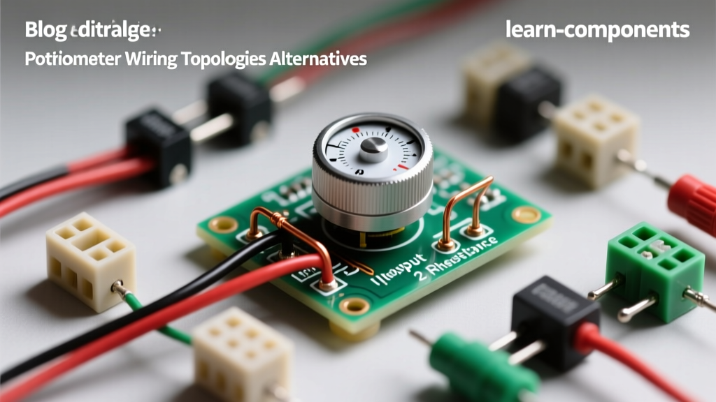
When makers, audio engineers, and industrial technicians ask, "how do you wire a potentiometer," the answer is rarely a single solution. A potentiometer (often called a "pot") is fundamentally a three-terminal resistor with a sliding or rotating wiper that forms an adjustable voltage divider. However, depending on whether you are reading an analog sensor with a microcontroller, dimming a high-power LED, or designing a failsafe analog control loop, the wiring topology changes drastically.
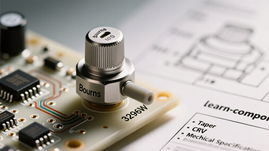
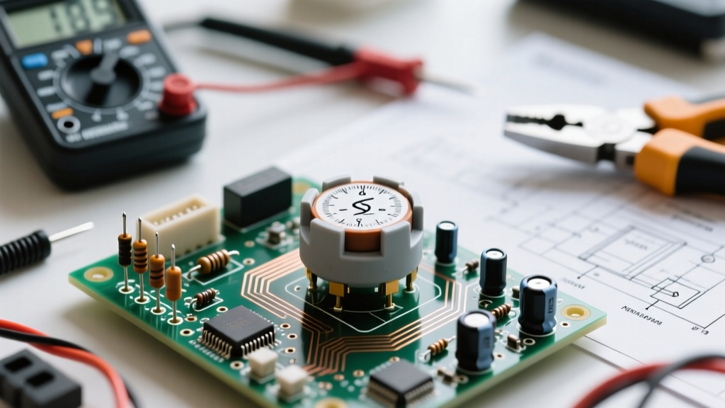
Before diving into the configurations, let us establish the standard pinout for a typical 10kΩ carbon-film rotary potentiometer (like the widely used Alps RK09K series) or a cermet trimpot (like the Bourns 3296W). Facing the shaft with the terminals pointing down:
- Pin 1 (Left): Counter-Clockwise (CCW) terminal
- Pin 2 (Center): The Wiper (the variable output)
- Pin 3 (Right): Clockwise (CW) terminal
Understanding these three nodes is the key to mastering the three primary wiring topologies and knowing when to abandon mechanical pots for solid-state alternatives.
Topology 1: The Voltage Divider (3-Terminal Wiring)
The most common answer to "how do you wire a potentiometer" is the voltage divider configuration. This method uses all three terminals to translate mechanical rotation into a variable voltage signal, making it ideal for microcontroller ADC (Analog-to-Digital Converter) inputs, audio volume controls, and synthesizer modulation.
Wiring Instructions:
- Connect Pin 1 to your reference voltage (e.g., 5V or 3.3V).
- Connect Pin 3 to Ground (GND).
- Connect Pin 2 (Wiper) to your signal input (e.g., Arduino A0 pin).
The Engineering Reality: According to SparkFun's Voltage Divider Tutorial, the output voltage is determined by the ratio of the resistances on either side of the wiper. However, when wiring a pot to a microcontroller like the ATmega328P, you must consider source impedance. The internal sample-and-hold capacitor of the ADC requires a low-impedance source to charge fully within the sampling window. If you use a 1MΩ potentiometer, your ADC readings will be erratic and non-linear. Always default to a 10kΩ linear (B-taper) potentiometer for microcontroller wiring to keep the source impedance well below the recommended 10kΩ maximum threshold.
Topology 2: The Rheostat (2-Terminal Variable Resistor)
What if you do not need a variable voltage, but rather a variable resistance to limit current? This is where the rheostat topology comes in. By ignoring one of the end terminals, you turn the three-terminal device into a two-terminal variable resistor.
Wiring Instructions:
- Connect Pin 1 in series with your load (e.g., an LED or small DC motor).
- Connect Pin 2 (Wiper) to the other side of your circuit loop.
- Leave Pin 3 completely unconnected (floating).
Critical Warning: Never wire a standard 10kΩ carbon-film potentiometer as a rheostat to control high-current loads like 12V DC motors or high-power LED arrays. The wiper contact is typically rated for only 50mA to 100mA. Pushing 500mA through the wiper will vaporize the carbon track, resulting in catastrophic open-circuit failure. For high-current rheostat applications, you must use wire-wound potentiometers (like the Vishay 534 series), which can handle 2A+ but cost upwards of $15.00 compared to a $0.50 carbon film pot.
Topology 3: The "Wiper-to-End" Failsafe Method
In industrial environments or high-voltage analog control loops, mechanical wear is a severe liability. Over time, the carbon or cermet track degrades, and the wiper can momentarily lose physical contact with the resistive element. In a standard rheostat wiring (Topology 2), a wiper bounce creates an open circuit (infinite resistance). If this pot is controlling the feedback loop of a high-power motor driver, an open circuit could cause the motor to runaway to maximum speed, destroying the machinery.
The Failsafe Wiring Solution:
To prevent this, we use a clever wiring trick detailed in All About Circuits' section on Potentiometers.
- Wire the circuit using the Rheostat method (Pin 1 and Pin 2).
- Short Pin 2 (Wiper) and Pin 3 together using a jumper wire or solder bridge.
Why this works: If the wiper loses contact due to track wear or vibration, the current simply flows through the short to Pin 3. Instead of the circuit seeing infinite resistance (an open circuit), it sees the maximum rated resistance of the potentiometer (e.g., 10kΩ). This gracefully defaults the circuit to a "safe" minimum-current state rather than a dangerous runaway state.
Component Alternatives: When Standard Potentiometer Wiring Falls Short
Sometimes, the answer to "how do you wire a potentiometer" is "you shouldn't." Mechanical pots suffer from wiper bounce, thermal noise, and physical wear (typically rated for only 10,000 to 100,000 rotation cycles). Let us compare the standard mechanical pot to modern alternatives based on wiring complexity, cost, and lifespan.
| Component Type | Example Model | Avg. Cost (2026) | Wiring Complexity | Lifespan / Cycles | Best Use Case |
|---|---|---|---|---|---|
| Carbon Rotary Pot | Alps RK09K (10k) | $0.50 | Low (3 analog wires) | ~15,000 cycles | Audio volume, basic user inputs |
| Cermet Trimpot | Bourns 3296W | $1.20 | Low (3 analog wires) | ~200 cycles | One-time PCB calibration |
| Rotary Encoder | KY-040 Module | $1.50 | Medium (5 digital wires + interrupts) | ~100,000+ cycles | Digital menus, infinite rotation |
| Digital Potentiometer | Microchip MCP41010 | $2.10 | High (SPI bus + decoupling caps) | Infinite (Solid State) | Automated gain control, IoT |
The Verdict on Alternatives: If you are designing a product that requires a user to adjust a setting daily for five years, abandon the mechanical potentiometer. Wire a Rotary Encoder instead. Encoders output digital quadrature pulses, eliminating analog noise and wiper degradation entirely. If your system requires automated calibration without human intervention, wire an SPI-based Digital Potentiometer, which uses internal MOSFET ladders to change resistance via microcontroller commands.
Wiring Failures and Troubleshooting Matrix
Even when you know exactly how to wire a potentiometer, real-world physics introduces noise and failure modes. Use this troubleshooting matrix to diagnose wiring and component issues:
- Symptom: "Scratchy" or popping audio when turning the knob.
Diagnosis: Carbon dust accumulation or oxidation on the track.
Fix: Do not rewire. Inject a specialized contact cleaner (like DeoxIT FaderLube) into the wiper slot and rotate 50 times. - Symptom: Erratic, jumping ADC values on a microcontroller.
Diagnosis: Wiper bounce or high-frequency EMI coupling into the high-impedance wiper pin.
Fix: Wire a 100nF ceramic bypass capacitor directly between the Wiper (Pin 2) and Ground. This creates a hardware low-pass filter that smooths out microsecond wiper bounces. - Symptom: Volume increases too fast at the beginning of the rotation.
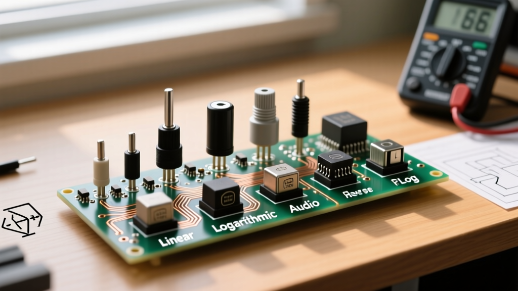
Diagnosis: Incorrect taper wiring. You likely wired a Logarithmic (Audio/A-taper) pot backwards.
Fix: Swap the wires on Pin 1 and Pin 3. This reverses the physical direction of the resistive curve without changing the component.
Final Decision Framework: Which Wiring Method Should You Choose?
To summarize your prototyping decisions:
- Choose the Voltage Divider (3-Pin) when you need to feed a variable 0-5V signal into an Arduino, ESP32, or op-amp. Always use 10kΩ linear (B-taper) pots to satisfy ADC impedance requirements.
- Choose the Rheostat (2-Pin) only for low-current signal trimming or when using heavy-duty wire-wound pots for power applications.
- Choose the Failsafe Short (Wiper-to-End) in any mission-critical, high-voltage, or industrial environment where an open-circuit failure could damage downstream equipment.
- Pivot to Digital Alternatives when mechanical wear, infinite rotation, or remote IoT control are primary design constraints.
Mastering how to wire a potentiometer is not just about connecting three pins; it is about understanding the electrical topology, the mechanical limitations of the wiper, and the specific demands of your load. Wire intelligently, filter your signals, and your analog interfaces will perform flawlessly for years.