
The Anatomy of a Potentiometer: Beyond the Schematic Symbol
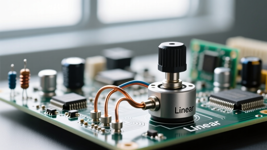
When most beginners encounter a potentiometer (often abbreviated as a "pot"), they view it simply as a variable resistor or a volume knob. However, in practical circuit design, a potentiometer is fundamentally a three-terminal electromechanical voltage divider. Understanding the physical construction and material science behind the resistive track is critical for selecting the right component for your specific application, whether you are designing a precision sensor interface or a high-fidelity audio preamplifier.
Inside a standard rotary potentiometer, a wiper arm slides across a resistive track. The material of this track dictates the component's noise floor, lifespan, and power dissipation capabilities. According to All About Circuits, the three most common track materials are carbon composition, cermet (ceramic and metal), and conductive plastic.
- Carbon Composition: Found in cheap audio pots and standard panel-mount dials (e.g., Alpha 16mm pots). They offer high resolution but suffer from current noise and track wear over time.
- Cermet: The standard for precision trimming. The Bourns 3296W is a classic cermet multi-turn trimpot (costing around $1.20) used on PCBs for calibration. Cermet handles higher temperatures and offers excellent stability.
- Wirewound: Constructed from nichrome or similar resistance wire. They handle high power (up to 5W or more) but have finite resolution due to the discrete wire turns, causing a "stepped" output rather than a smooth analog sweep.
Single-Turn Panel Pots vs. Multi-Turn Trimpots
For user-facing interfaces (like a stereo volume knob), a single-turn pot (usually spanning 270 to 300 degrees of rotation) is ideal. However, for circuit calibration where precision is paramount, multi-turn trimpots are mandatory. A standard 25-turn cermet trimpot requires 9,000 degrees of rotation to traverse the full resistive track, allowing engineers to dial in exact reference voltages with sub-millivolt accuracy. The trade-off is mechanical complexity and a higher price point, with premium wirewound 10-turn pots like the Bourns 3590 costing upwards of $15.00 per unit.
Linear vs. Audio (Logarithmic) Tapers: Choosing the Right Curve
The "taper" of a potentiometer defines the mathematical relationship between the physical shaft rotation and the resulting resistance ratio. Selecting the wrong taper is the most common mistake in DIY audio and control circuits.
| Rotation Angle | Linear Taper (B10K) | Audio/Log Taper (A10K) | Reverse Audio (C10K) |
|---|---|---|---|
| 0% (CCW) | 0% | 0% | 100% |
| 25% | 25% | ~8% | ~92% |
| 50% (Center) | 50% | ~18% | ~82% |
| 75% | 75% | ~45% | ~55% |
| 100% (CW) | 100% | 100% | 0% |
Why does audio require a logarithmic taper? Human perception of sound pressure levels is logarithmic, not linear. If you use a linear B10K potentiometer for a volume control, the audio will sound like it jumps from silent to full volume in the last 20% of the knob's rotation, rendering the first 80% virtually useless. An audio taper (A10K) compensates for human hearing, providing a perceived linear increase in volume as you turn the knob.
Application 1: Precision Voltage Divider for MCU ADCs
Interfacing a potentiometer with a microcontroller's Analog-to-Digital Converter (ADC) is a foundational prototyping skill. The SparkFun Voltage Divider Tutorial outlines the basic wiring, but real-world implementation requires understanding source impedance.
The 3-Terminal Wiring Configuration
To use a pot as a voltage divider, connect Terminal 1 to your reference voltage (e.g., 5V or 3.3V), Terminal 3 to Ground, and the Wiper (Terminal 2) to the microcontroller's ADC input pin. As you rotate the shaft, the wiper outputs a variable voltage between 0V and Vref.
Solving the "Jittery ADC" Problem with Impedance Matching
A frequent issue in Arduino (ATmega328P) and ESP32 projects is a jittery, unstable ADC reading, even when the potentiometer is left untouched. This is caused by high source impedance. The ATmega328P datasheet explicitly recommends an ADC source impedance of 10kΩ or less to ensure the internal sample-and-hold capacitor charges fully during the acquisition window.
If you use a 10kΩ potentiometer, what is the actual source impedance? The Thevenin equivalent resistance looking into the wiper is the parallel combination of the upper and lower track resistances (R1 || R2). The maximum impedance occurs at the exact center of the track (5kΩ || 5kΩ), which equals 2.5kΩ. This is well within the 10kΩ microcontroller limit. However, if you mistakenly use a 100kΩ pot to "save power," your peak source impedance jumps to 25kΩ, leading to incomplete capacitor charging and erratic digital readings.
RC Low-Pass Filtering for Noise Rejection
Even with correct impedance, electromagnetic interference (EMI) can induce noise on the wiper trace. To create a hardware low-pass filter, solder a 100nF ceramic capacitor directly between the ADC pin and ground. Combined with the 2.5kΩ Thevenin resistance at the wiper's midpoint, this creates an RC filter with a cutoff frequency of approximately 636Hz, effectively stripping out high-frequency RF noise without introducing noticeable latency to user inputs.
Application 2: Audio Volume Control and Grounding Loops
When wiring an A10K audio taper potentiometer for an analog audio signal path, grounding topology is critical. Never use the potentiometer's metal chassis as your primary signal ground return, as this invites ground loops and 50/60Hz mains hum. Instead, use a dedicated star-grounding scheme. Solder the signal ground wire directly to Terminal 3 of the pot, and run a separate, isolated shield ground to the metal casing to act as a Faraday cage against radio frequency interference (RFI).
Expert Prototyping Tip: When wiring audio pots, keep the ungrounded signal wires (from Terminal 1 to your amplifier input) as short as physically possible. Long, unshielded wires acting as the "hot" signal path will act as antennas, picking up switching noise from nearby digital circuits or power supplies.
Common Failure Modes and Troubleshooting
Potentiometers are mechanical components, meaning they are subject to physical degradation. Understanding failure modes helps in diagnosing circuit anomalies.
Track Wear and Contact Noise (The "Scratchy" Pot)
The most ubiquitous failure in carbon-track potentiometers is the accumulation of oxidation, dust, and microscopic carbon debris on the resistive element. This manifests as a loud "scratchy" or "popping" noise in audio circuits, or sudden value jumps in sensor applications.
The Fix: Do not use standard WD-40 or isopropyl alcohol, as these can leave residues or fail to clear heavy oxidation. The industry standard is CAIG DeoxIT D5. This specialized contact cleaner contains mild solvents that dissolve oxidation and leave a microscopic, non-conductive protective film that prevents future tarnishing while lubricating the wiper contact.
Wiper Lift and Open Circuits
If a potentiometer is subjected to excessive mechanical force or operated beyond its rotational torque limits, the wiper spring can fatigue. This results in "wiper lift," where the contact momentarily leaves the resistive track. In a voltage divider circuit, this causes the output voltage to float unpredictably or snap to the VCC rail, which can be disastrous if that signal is driving a sensitive gate voltage on a power MOSFET. To prevent this in critical industrial applications, engineers often place a high-value pull-down resistor (e.g., 1MΩ) on the ADC input to ensure the pin defaults to a safe 0V state if the wiper connection opens.