
Beyond the Picture: Decoding Potentiometer Anatomy
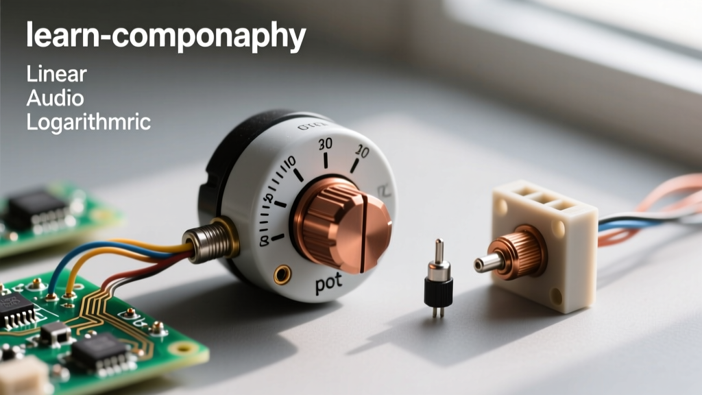
When a beginner searches for a picture of a potentiometer, they are often met with a confusing array of blue cubes, silver dials, and wirewound cylinders. While a simple photograph shows the exterior casing, true component identification requires understanding the internal topology, mechanical form factor, and electrical markings that define how the part behaves in a circuit.
At its core, a potentiometer (or 'pot') is a three-terminal resistor with a sliding or rotating contact that forms an adjustable voltage divider. However, the physical manifestation of this component varies wildly depending on its application. From the microscopic cermet trimpots hidden inside audio amplifiers to the heavy-duty wirewound dials used in industrial motor controls, visual identification is the first step in successful prototyping and repair.
In this component identification guide, we will break down the visual cues, alphanumeric stamps, and mechanical footprints of the most common potentiometers used in modern electronics, ensuring you never misidentify a logarithmic audio taper for a linear voltage control again.
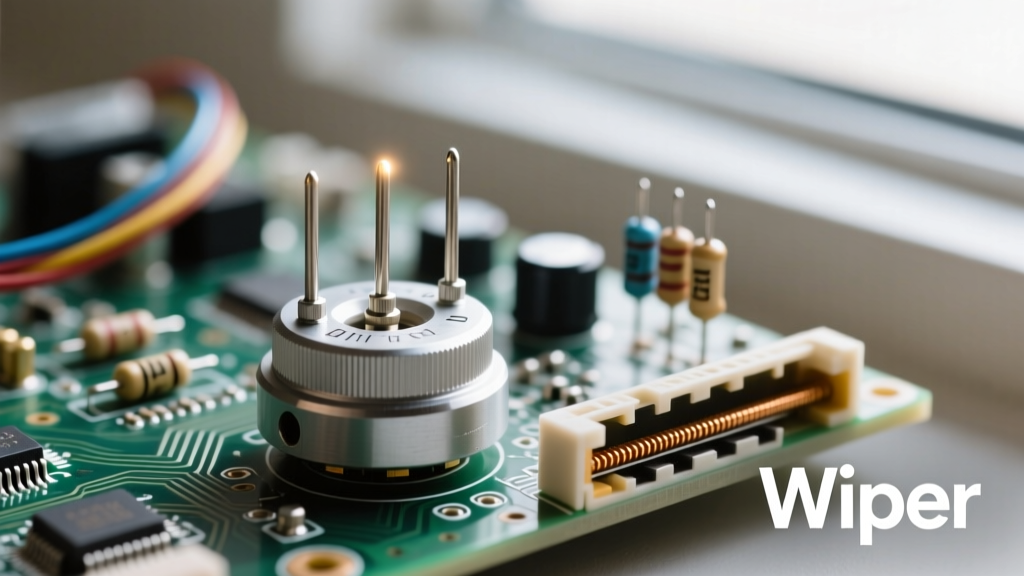
The Three-Terminal Pinout: Wiper, CCW, and CW
Regardless of whether you are looking at a top-view picture of a potentiometer or examining it in your hand, the three-terminal layout remains consistent. Understanding this physical layout is critical before you ever apply a soldering iron.
- Terminal 1 (CCW - Counter-Clockwise): Typically the leftmost pin when facing the shaft. Connected to one end of the internal resistive track.
- Terminal 2 (Wiper): The center pin. This is mechanically linked to the shaft and sweeps across the resistive element, providing the variable output voltage.
- Terminal 3 (CW - Clockwise): The rightmost pin. Connected to the opposite end of the resistive track.
Voltage Divider vs. Rheostat Wiring
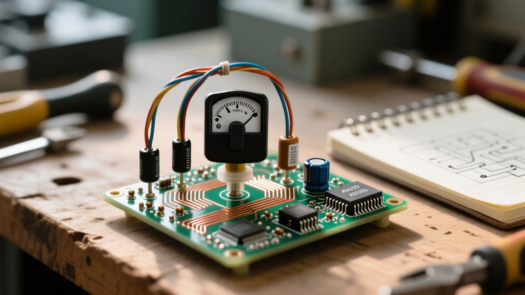
Visually identifying the wiper pin (the center terminal) dictates your wiring strategy. If you need a voltage divider (e.g., reading an analog sensor with a microcontroller or controlling audio volume), you must use all three terminals. If you only need a variable resistor or rheostat (e.g., adjusting the gain on an op-amp or dimming a simple LED circuit), you will visually jumper the wiper to either the CW or CCW terminal. This ensures that if the wiper loses contact due to internal wear, the circuit defaults to maximum resistance rather than dropping to zero ohms and potentially shorting your power supply.
Visual Taper Identification: Decoding the Alpha-Numeric Stamp
The most critical piece of information hidden in plain sight on the metal casing or bakelite backplate is the taper code. The taper defines the mathematical relationship between the shaft's physical rotation and the electrical resistance output. Misidentifying the taper is the most common mistake in DIY audio and synthesizer builds.
Manufacturers stamp a combination of letters and numbers onto the housing. For example, you might see B10K or A50K. Here is how to decode the visual stamps based on global standards:
| Letter Code | Taper Type | Primary Application | Visual/Physical Cue |
|---|---|---|---|
| B (Asian/EU) | Linear | Voltage dividers, sensor scaling, LED dimming | Resistance changes at a constant rate per degree of rotation. |
| A (Asian/EU) | Logarithmic (Audio) | Audio volume controls, guitar pedals | Slow resistance change at the start of the sweep, rapid at the end. |
| C | Reverse Logarithmic | Specialized audio panning, tone controls | Rapid change early in the sweep, flattening out later. |
| W | Linear (Multi-turn) | Precision calibration, trimpots | Usually found on blue cermet cubes with a brass adjustment screw. |
Note: Vintage American equipment (like older Fender amplifiers) sometimes used an inverted standard where 'A' meant Linear and 'B' meant Logarithmic. Always verify with a multimeter if restoring vintage gear.
Trimpots vs. Panel Mounts: Form Factor Visuals
When browsing a supplier catalog, the pictures of potentiometers generally fall into two distinct mechanical categories: Panel Mounts and Trimpots (Trimming Potentiometers).
Panel Mount Potentiometers
These are designed for user interaction. A classic example is the Bourns PTV09A series or the ubiquitous ALPS RK09 found in mixing consoles. Visually, they feature a protruding shaft (typically 6mm metric or 1/4-inch imperial for guitar pedals) meant to accept a plastic or metal knob. The rear housing is usually enclosed in a metal shield to protect the internal carbon or conductive plastic track from dust and static discharge.
Prototyping Warning: The solder lugs on standard panel mount pots are spaced at 0.2 inches (5.08mm). They will not fit directly into a standard 0.1-inch breadboard. To prototype with these, you must either solder jumper wires to the lugs or use a dedicated PCB breakout board.
Trimpots (Trimming Potentiometers)
Trimpots are designed for 'set-and-forget' calibration by technicians, not daily user interaction. The most iconic visual is the Bourns 3296W multi-turn trimpot. It appears as a small blue epoxy or cermet cube with a brass slotted screw on the top or side. According to the Bourns 3296 series datasheet, these components require up to 25 full turns of the screw to traverse the entire resistive track, allowing for microscopic precision when setting bias voltages on transistors or calibrating sensor thresholds.
Unlike panel mounts, the pins on a 3296W trimpot are spaced at exactly 0.1 inches (2.54mm), making them perfectly compatible with standard solderless breadboards for rapid prototyping.
Internal Composition: Carbon vs. Cermet vs. Wirewound
While you cannot see the internal track without destroying the component, the external casing often provides visual clues about the resistive material used inside.
- Carbon Composition: Usually housed in stamped metal or bakelite casings. These offer low noise and smooth transitions, making them the undisputed choice for audio signal paths. However, they are susceptible to moisture and physical wear.
- Cermet (Ceramic + Metal): Almost exclusively used in trimpots (the blue cubes). Cermet tracks can withstand high temperatures, making them ideal for wave-soldering processes and high-power calibration circuits where a carbon track would literally burn up.
- Wirewound: Visually, these are often large, heavy, and cylindrical with a humped or ribbed casing (like the Vishay 534 series). Inside, a nichrome wire is wound around a ceramic core. They handle high wattage (5W to 25W+) but suffer from 'stepped' resolution and inductance, making them terrible for high-frequency audio but excellent for heavy-duty motor speed controls.
Visual Diagnostics: Spotting Failure Modes
An experienced technician can often diagnose a failing potentiometer just by looking at it and performing a simple mechanical test. As noted in the All About Circuits textbook chapter on rheostats, mechanical wear is the primary enemy of variable resistors.
The 'Scratchy' Audio Test: If rotating the shaft of an audio volume knob produces a static 'scratching' or 'popping' sound through the speakers, the internal carbon track has likely accumulated conductive dust or suffered from wiper oxidation. While a visual inspection from the outside won't show this, shining a flashlight into the small ventilation slots on the metal casing can sometimes reveal dark, oxidized smudges near the wiper contact point.
Visual Red Flags for Replacement:
- Wobbly Shafts: If the shaft has lateral play, the internal bushing is worn. The wiper will bounce off the track during use, causing signal dropouts.
- Cracked Bakelite: Common in vintage gear. If the casing around the mounting nut is cracked, the internal alignment of the resistive track is compromised.
- Oxidized Solder Lugs: If the terminals appear dull, grey, or pitted, the pot has been exposed to high humidity. This can lead to cold solder joints even if the internal track is perfectly fine.
Summary Checklist for Component ID
Next time you are looking at a picture of a potentiometer or holding one at your workbench, run through this rapid identification checklist:
- Count the Pins: 3 pins = standard pot. 5 or 6 pins = likely a dual-gang (stereo) pot or a pot with an integrated push-switch (common in modern guitar volume knobs).
- Read the Stamp: Identify the 'A' or 'B' prefix to determine if it is Audio (Log) or Linear.
- Check the Pin Spacing: 0.1-inch for breadboard trimpots, 0.2-inch for panel mount solder lugs.
- Note the Shaft Type: Round (requires set-screw knobs) vs. D-Cut (requires push-on knobs with a flat side for grip).
By mastering these visual and mechanical identifiers, you bridge the gap between simply looking at a component and truly understanding how it will perform in your next electronic design. For more hands-on prototyping advice, check out the SparkFun Potentiometer Tutorial for excellent wiring diagrams and microcontroller integration tips.