
When designing a circuit or prototyping on a breadboard, engineers often focus heavily on the resistance value, taper (linear vs. logarithmic), and power rating of a variable resistor. However, the physical interface—the potentiometer pins—dictates your assembly process, mechanical reliability, and PCB layout constraints. Choosing the wrong terminal style can lead to mechanical stress on the component, poor solder joints, or a complete inability to fit the part into your enclosure.
This comprehensive buying guide breaks down the anatomy, materials, and form factors of potentiometer pins, giving you the exact specifications needed to select the right component for your Bill of Materials (BOM).
The Electrical Anatomy of Potentiometer Pins
Before evaluating the physical shape of the terminals, you must understand the electrical mapping of a standard 3-pin potentiometer. Regardless of the physical package, almost all standard single-turn potentiometers feature three terminals:
- Pin 1 (Terminal A / CCW): The counter-clockwise end of the resistive track. In many DC voltage divider applications, this is tied to Ground (GND).
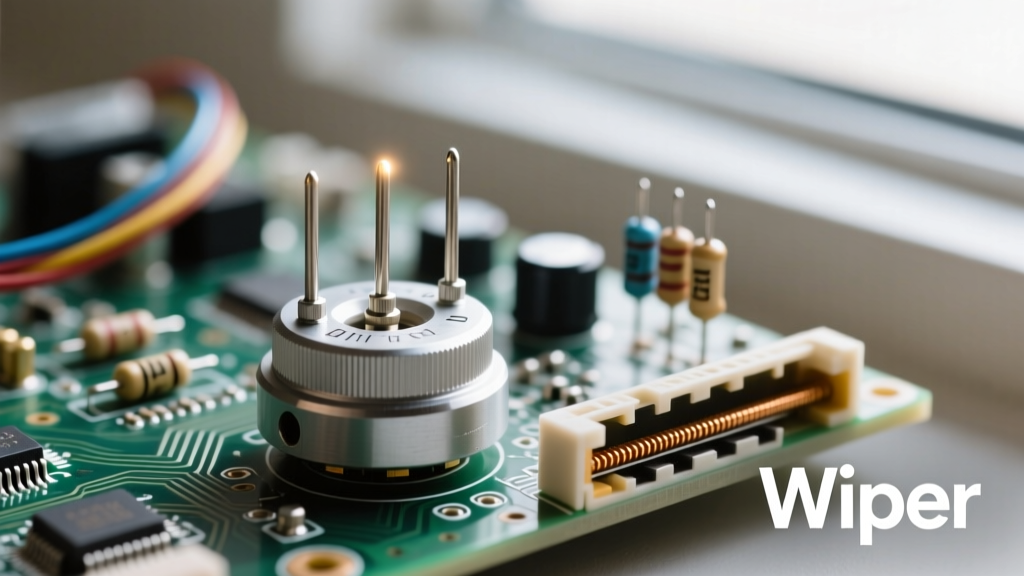
- Pin 2 (Wiper): The movable contact that sweeps across the resistive element. This is your output signal or variable voltage node.
- Pin 3 (Terminal B / CW): The clockwise end of the resistive track. Typically tied to the positive supply voltage (VCC).
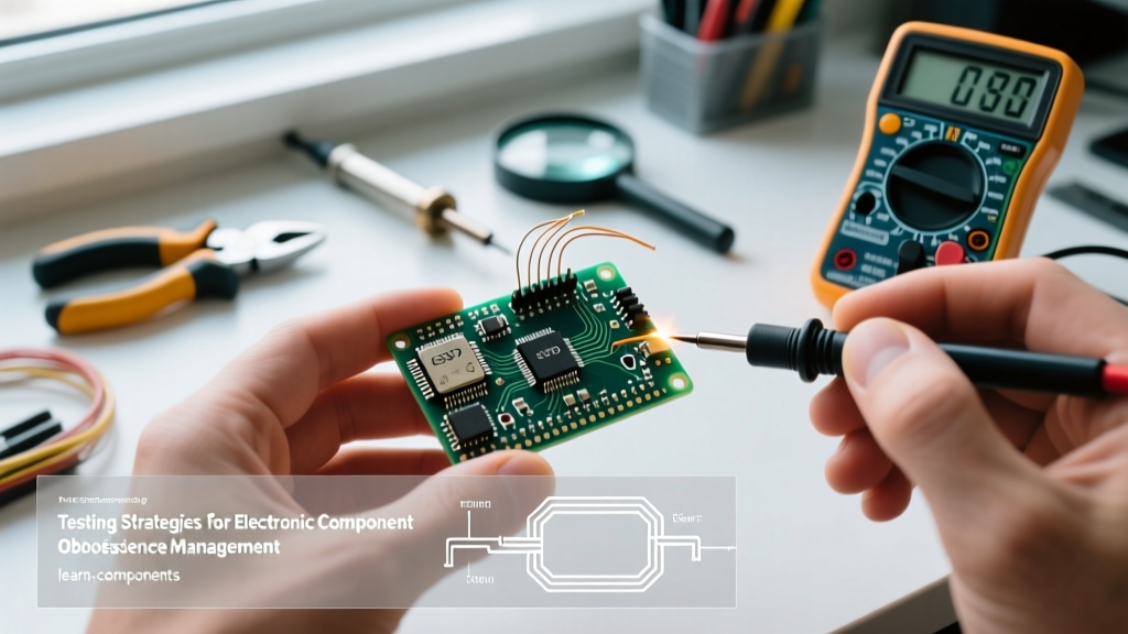
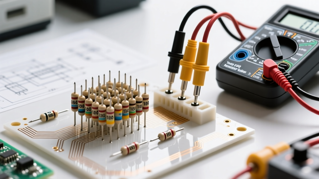
Pro-Tip for Prototyping: Pin numbering is not universally standardized across all manufacturers. Always use a digital multimeter in continuity or resistance mode to identify Pin 2 (the wiper). Measure the resistance between pairs of pins while turning the shaft. The pin that shows a changing resistance value relative to the other two is your wiper.
PCB Mount vs. Panel Mount: Pin Configuration Breakdown
The first major purchasing decision involves how the potentiometer pins will interface with your hardware. This choice defines whether the component is mounted directly to the printed circuit board or to the chassis of your device.
Through-Hole PC Pins (Straight and Right-Angle)
PC (Printed Circuit) pins are flat, stamped metal legs designed to pass through plated through-holes (PTH) on a PCB. Straight PC pins are ideal for breadboarding and standard top-down PCB layouts. Many 9mm and 16mm potentiometers feature a 0.1-inch (2.54mm) or 0.2-inch (5.08mm) pin pitch, allowing them to plug directly into standard solderless breadboards.
Right-angle PC pins bend 90 degrees from the base. These are critical for edge-mounted designs where the shaft must protrude through the side panel of an enclosure while the body remains flat against the PCB, saving vertical Z-axis clearance.
Solder Lugs for Panel Mounting
Solder lugs are elongated, robust metal tabs with a hole or notch at the end. They are designed for panel-mount potentiometers where the chassis absorbs the mechanical stress of the user turning the knob. Solder lugs require manual wiring (usually AWG 22-26 stranded wire) rather than direct PCB insertion. This decoupling prevents PCB trace tearing if the user applies heavy lateral force to the knob.
SMD (Surface Mount) Terminals
For high-volume, automated manufacturing, SMD potentiometer pins are formed into gull-wing or J-lead configurations. These are soldered directly to surface pads using reflow ovens. They are common in compact consumer electronics but are notoriously difficult to hand-solder during the prototyping phase.
Comparison Chart: Common Potentiometer Pin Styles
Use the table below to match your mechanical requirements with the correct terminal style.
| Pin Style | Typical Pitch / Spacing | Best Application | Example Series |
|---|---|---|---|
| Straight PC Pin | 2.54mm / 5.08mm | Breadboarding, Standard PCB | Bourns 3386, Alpha 9mm |
| Right-Angle PC Pin | 2.54mm / 5.0mm | Edge-mount, Low-profile enclosures | Bourns 3296X, TT Electronics |
| Solder Lugs | N/A (Wire attached) | Heavy-duty panel mount, Audio mixers | ALPS Alpine RK27, CTS |
| SMD Gull-Wing | Varies (e.g., 4.5mm) | Automated SMT assembly, Wearables | Bourns 3313, Panasonic |
Material Science: Pin Plating and Base Alloys
The metallurgy of potentiometer pins directly impacts solderability, shelf life, and long-term reliability. When reviewing a datasheet, pay close attention to the terminal material specifications.
Base Alloys: Brass vs. Phosphor Bronze
Cheaper, off-brand potentiometers often use brass for their PC pins. While highly conductive, brass lacks spring tension and is prone to fatigue and snapping if bent during manual assembly. Premium manufacturers like Bourns and ALPS Alpine utilize phosphor bronze or beryllium copper. These alloys offer superior mechanical strength, ensuring the pins remain rigid during wave soldering and insertion into tight breadboard sockets.
Terminal Plating Options
- Matte Tin: The industry standard for RoHS-compliant components. It offers excellent solderability and a long shelf life, though it is susceptible to tin whisker growth over many years in high-humidity environments.
- Tin-Lead (SnPb): Still used in aerospace and military applications (COTS components) to prevent tin whiskers and ensure flawless wetting with leaded solder pastes.
- Gold Flash: Found on high-end audio potentiometers and precision trimmers. Gold prevents oxidation and ensures the lowest possible contact resistance, which is vital when dealing with low-level audio signals where micro-ohm variations cause audible noise.
Thermal Limits and Soldering Failure Modes
One of the most common causes of component failure in DIY and prototyping environments is thermal damage to the potentiometer pins during soldering. The internal wiper carrier is typically made of high-temperature thermoplastics, and the resistive track (especially in carbon composition pots) is sensitive to extreme heat.
Most datasheets specify a maximum manual soldering temperature of 350°C (662°F) for a maximum of 3 seconds per pin. If you apply a soldering iron to Pin 2 (the wiper) for too long, the heat will travel up the metal terminal and melt the internal plastic wiper carrier. This results in a permanent mechanical bind, wiper noise, or an open circuit.
Wave Soldering Considerations: If you are designing for automated wave soldering, ensure the PCB layout includes thermal relief pads and that the component body sits at least 1.5mm above the board surface to prevent flux and molten solder from wicking up the pins and sealing the internal shaft mechanism.
Procurement: Top Series for Your BOM
When sourcing potentiometers, relying on established series ensures you have access to accurate 3D CAD models, precise footprint dimensions, and consistent pin tolerances.
- Bourns 3296 Series (Trimpots): The gold standard for PCB-mounted precision trimming. Available in W (top-adjust), X (side-adjust right-angle), and P (top-adjust with different pin spacing) configurations. Pin spacing is strictly 0.100" (2.54mm) for easy routing.
- ALPS Alpine RK09 Series: A staple in audio equipment. These 9mm single-turn pots feature robust PC pins designed to withstand the mechanical torque of heavy aluminum knobs. They typically use a 5.0mm pitch for the outer pins and a centered wiper pin.
- TT Electronics P23 Series: Excellent for panel-mount applications requiring solder lugs, featuring high rotational torque and ruggedized terminal tabs that resist bending during hand-wiring.
Final Thoughts on PCB Layout
When designing your PCB footprint for potentiometer pins, never rely solely on generic software libraries. Always download the manufacturer's specific datasheet and verify the X and Y pin coordinates. A discrepancy of just 0.5mm in pin spacing will force you to bend the phosphor bronze legs, introducing mechanical stress that can eventually crack the solder joint after repeated thermal cycling. By carefully selecting the right pin style, material, and orientation, you ensure your variable resistors provide smooth, reliable control for the lifetime of your device.
For more foundational knowledge on voltage dividers and sensor integration, refer to resources like Electronics Tutorials to deepen your understanding of how these physical pins translate into analog circuit behavior.