
When troubleshooting a mixed-signal control board or repairing a vintage audio amplifier, the schematic diagram is your primary map. However, truly understanding the symbol of a potentiometer requires bridging the gap between theoretical schematic representation and physical, real-world testing. A schematic symbol implies an ideal, continuous variable resistance, but physical components suffer from track wear, wiper noise, and tolerance drift. As an electronics technician, your ability to translate the symbol on the page into actionable multimeter and oscilloscope measurements is what separates a parts-swapper from a true diagnostician.
Anatomy of the Potentiometer Symbol on Schematics
Before you touch your test probes to the circuit, you must accurately identify the component's topology on the schematic. The symbol of a potentiometer varies slightly depending on the drafting standard used by the engineer, but the core functional representation remains consistent.
IEEE/ANSI vs. IEC Standard Symbols
In North America, schematics typically follow the IEEE/ANSI standard, representing the base resistive element as a zig-zag line. In Europe and most international industrial documentation, the IEC 60617 standard is used, which replaces the zig-zag with a simple rectangle. In both cases, the defining feature of the potentiometer symbol is the wiper arrow intersecting the resistive element.
| Standard | Resistor Base Shape | Wiper Indicator | Common Application |
|---|---|---|---|
| IEEE / ANSI | Zig-zag line | Diagonal or perpendicular arrow | Consumer electronics, US military/aerospace |
| IEC 60617 | Hollow rectangle | Diagonal arrow crossing the box | Industrial automation, European automotive |
Identifying the Wiper Terminal (Pin 2)
The arrow in the symbol always represents the wiper—the movable contact that divides the total resistance into two series resistors. On a standard 3-terminal physical component (like a Bourns 3296W trimpot), the wiper is almost universally the middle pin. However, on schematics, the wiper arrow might be drawn pointing to the left, right, or even top of the resistor symbol. Always trace the arrow's tail to identify the exact net name or node it connects to in the circuit.
Translating the Symbol to Physical Multimeter Testing
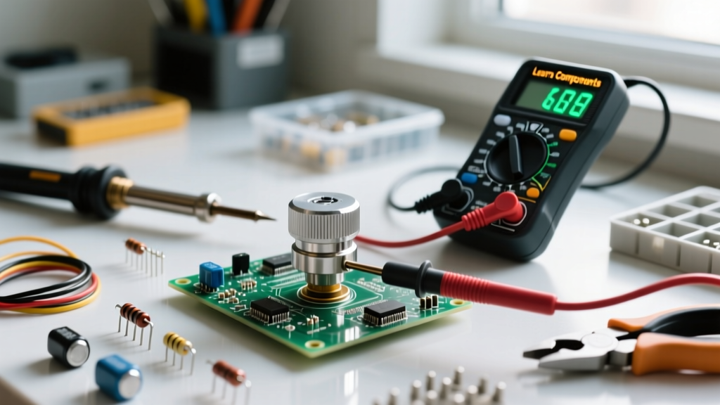
Once you have identified the symbol of a potentiometer on the schematic, you must map it to the physical pins on the PCB. Testing requires isolating the component whenever possible, as parallel circuit paths will skew your resistance readings.
Step 1: Measuring Total Resistance (Terminals 1 and 3)
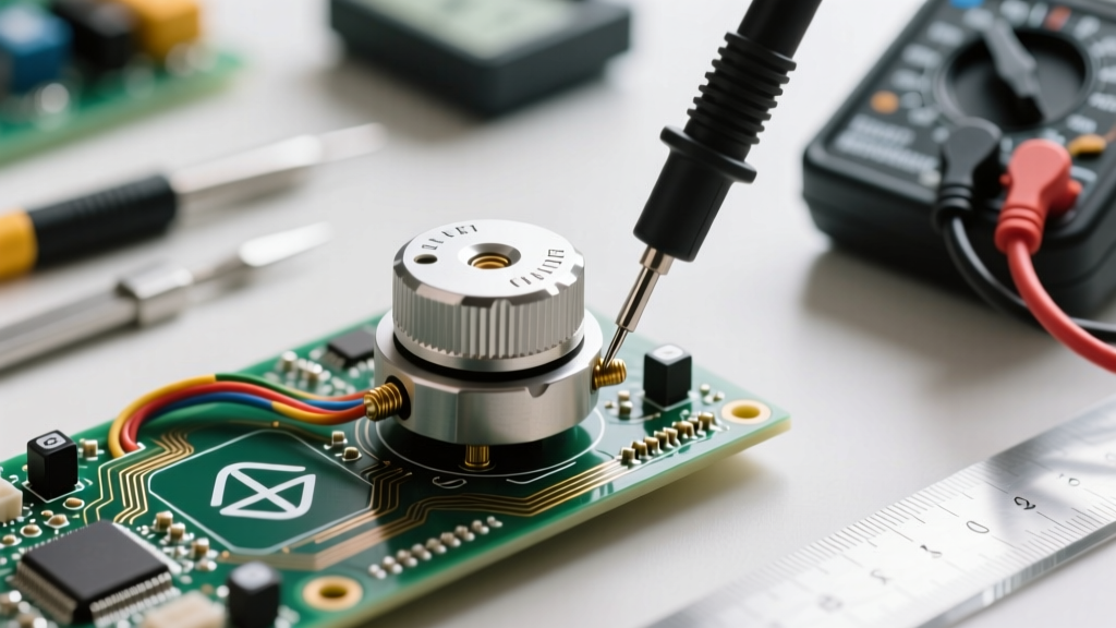
The ends of the resistor symbol (the points where the zig-zag or rectangle begin and end, ignoring the wiper arrow) represent the fixed terminals. Set your digital multimeter (DMM) to the appropriate resistance range. Place your probes on the two outer pins.
- Expected Reading: The nominal value of the pot (e.g., 10kΩ) plus or minus the manufacturer's tolerance (typically ±10% or ±20% for carbon, ±1% for precision cermet).
- Pro-Tip for Low-Value Pots: If testing a 100Ω wirewound pot, use your DMM's Relative (REL) mode. Short the probes together, press REL to zero out the lead resistance, and then measure. This prevents the 0.5Ω of your test leads from corrupting your data.
Step 2: Testing the Wiper Sweep (Terminals 1-2 and 2-3)
The wiper arrow in the schematic implies a smooth, continuous transition. To verify this physically, leave one probe on the wiper (Pin 2) and place the other on Pin 1. Slowly rotate the shaft or adjust the trim screw from one extreme to the other. The resistance should sweep smoothly from near 0Ω to the total nominal value. Repeat the process between Pin 2 and Pin 3; the sweep should occur in the opposite direction. According to Fluke's official testing guidelines, any sudden jumps to infinity (OL) during this sweep indicate a 'dead spot' where the wiper has lost physical contact with the resistive track.
Taper Indicators in Schematic Symbols
A standard symbol of a potentiometer does not inherently specify the taper (the mathematical relationship between shaft position and resistance ratio). However, detailed schematics often include a small graph or a letter designation (A, B, or C) adjacent to the symbol. Testing the taper is critical in applications like audio volume controls or motor speed ramps.
| Taper Type | Common Marking | Schematic Indicator | Testing at 50% Rotation |
|---|---|---|---|
| Linear | B (e.g., B10k) | Straight diagonal line or 'LIN' | ~50% of total resistance |
| Logarithmic (Audio) | A (e.g., A10k) | Curved line bowing inward or 'LOG' | ~10% to 15% of total resistance |
| Reverse Logarithmic | C or RA | Curved line bowing outward | ~85% to 90% of total resistance |
Measurement Technique: To test an Alps RK27 audio-taper potentiometer, set the shaft exactly to the mechanical midpoint. Measure the resistance between the wiper and the ground terminal. If the symbol indicates a logarithmic taper, but your multimeter reads 50% of the total value, the wrong component was installed during a previous repair, which will result in a highly non-linear and unusable volume control.
The Rheostat Configuration: Decoding the Two-Terminal Symbol
Sometimes, the symbol of a potentiometer on a schematic will show the wiper arrow shorted to one of the end terminals. This indicates a rheostat configuration, effectively turning the 3-terminal device into a 2-terminal variable resistor. Engineers use this to prevent an open-circuit failure if the wiper loses contact with the track.
Testing a Rheostat Configuration
When testing this configuration in-circuit or on the bench, you only probe the wiper and the un-shorted end terminal.
Diagnostic Insight: If you are troubleshooting a circuit and the schematic shows a standard 3-terminal pot, but the physical board has a jumper wire bridging the wiper and Pin 3, the designer likely revised the hardware to act as a rheostat to fix a noise or dropout issue found in earlier prototypes. Always trust the physical board layout over an outdated schematic revision.
Advanced Measurement: Catching Wiper Noise the Symbol Hides
The schematic symbol represents a mathematically perfect component. In reality, carbon composition potentiometers are highly susceptible to 'wiper noise'—microscopic fluctuations in resistance caused by dust, oxidation, or physical wear on the carbon track. A standard DMM might average out these fluctuations, showing a stable reading while the circuit experiences severe noise.
Using an Oscilloscope for Dynamic Testing
To truly validate the component against its ideal schematic symbol, inject a clean DC voltage (e.g., 5.00V) across Terminals 1 and 3. Connect your oscilloscope probe to the wiper (Terminal 2). As you slowly rotate the shaft, the oscilloscope trace should display a smooth, continuous ramp from 0V to 5V.
If you observe microsecond voltage spikes or dropouts on the scope trace, the potentiometer is suffering from track degradation. In high-precision sensor applications, such as a joystick axis feeding a 12-bit ADC, this noise will cause erratic data readings. The only remedy is replacing the component with a conductive plastic or multi-turn cermet alternative, such as those specified in Bourns precision potentiometer catalogs.
Summary Checklist for the Workbench
Before powering up a repaired board, run through this verification checklist based on the schematic symbol:
- Symbol Identification: Is it IEC or ANSI? Are there taper markings?
- Pin Mapping: Have you correctly identified the wiper net using the arrow?
- Static Resistance: Do the outer pins measure within tolerance of the schematic value?
- Dynamic Sweep: Does the wiper sweep smoothly without infinite dropouts?
- Configuration Check: Is it wired as a voltage divider (3 pins) or a rheostat (2 pins)?
By deeply understanding the symbol of a potentiometer and applying rigorous, multi-stage testing methodologies, you ensure that the physical hardware perfectly mirrors the engineer's theoretical design, resulting in reliable, noise-free circuit operation.