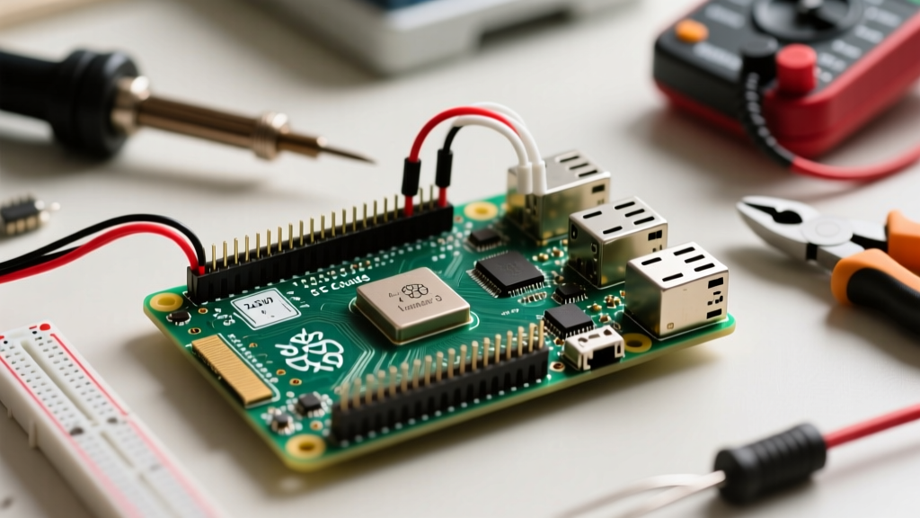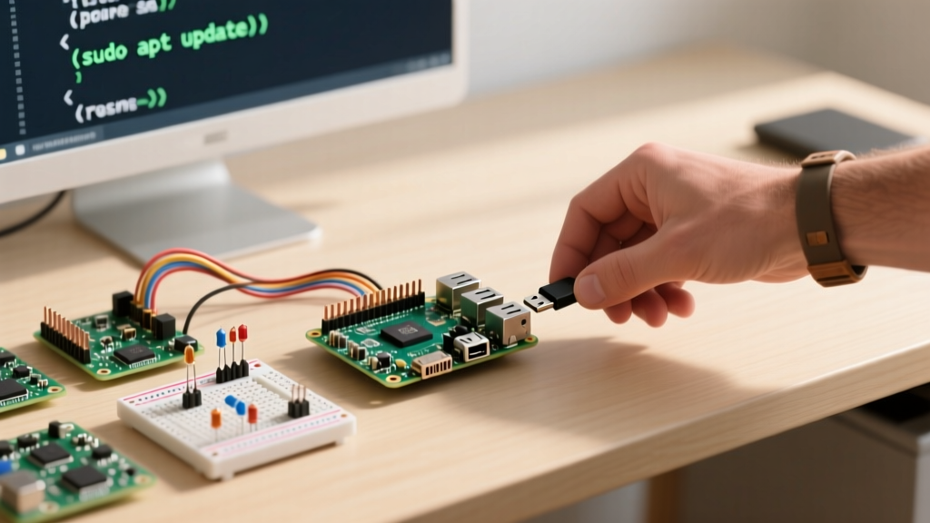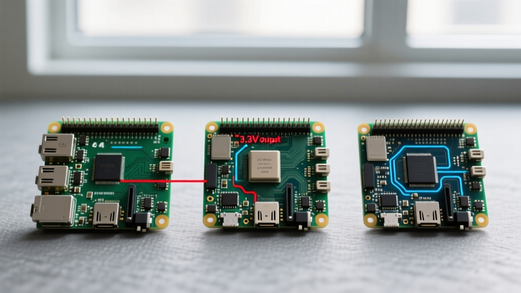

When building custom embedded systems, smart home controllers, or robotics platforms, understanding the physical and electrical nuances of your single-board computer's GPIO header is non-negotiable. While the 40-pin header has remained mechanically consistent since 2014, the underlying silicon driving those pins has evolved dramatically. In this hardware comparison, we dissect the Raspberry Pi 3 pin layout and contrast its electrical realities, protocol mappings, and power delivery limits against the newer Raspberry Pi 4 and Pi 5. Whether you are maintaining a legacy Pi 3 Model B+ fleet or planning a migration, this guide highlights the critical hardware differences that can make or break your DIY wiring.
Anatomy of the Raspberry Pi 3 Pin Layout
The Raspberry Pi 3 (both Model B and B+) utilizes a 2x20 male pin header. Physically, the Pinout.xyz diagram for the Pi 3 maps perfectly to the Pi 4 and Pi 5. Pin 1 (3.3V) and Pin 2 (5V) anchor the top left, while the ground pins are distributed across the outer edges to minimize return-path inductance. However, physical equivalence does not guarantee electrical parity. The Pi 3 is powered by the Broadcom BCM2837 (or BCM2837B0 on the B+), which routes GPIO signals directly through the SoC's internal multiplexers. This direct routing makes the Pi 3 highly susceptible to voltage droop and core-clock scaling artifacts—issues that were later mitigated in newer architectures.
The UART Bottleneck: PL011 vs. Mini-UART
One of the most notorious hardware quirks of the Raspberry Pi 3 pin layout involves the UART interface on Pins 8 (TX) and 10 (RX). On the Pi 3, the primary hardware UART (PL011) is hardwired to the onboard Bluetooth module. Consequently, the GPIO header is left with the 'mini-UART', which has a critical flaw: its baud rate is tied to the SoC's core clock frequency. If your Pi 3 thermally throttles or dynamically scales its CPU, the core clock shifts, instantly corrupting your serial data stream.
Hardware Workarounds for Pi 3 Serial
To restore the stable PL011 UART to the Raspberry Pi 3 pin layout header, you must disable the Bluetooth module by adding dtoverlay=disable-bt to your /boot/config.txt. In contrast, the Raspberry Pi 4 and Pi 5 feature additional dedicated UART channels, allowing both Bluetooth and stable GPIO serial communication to operate simultaneously without sacrificing the primary hardware UART.
Power Rail Tolerances and Backpowering Risks
A frequent point of failure in DIY projects is mismanaging the power pins on the 40-pin header. The 5V pins (Pins 2 and 4) on the Pi 3 are connected directly to the 5V input rail, sitting behind a polyfuse (rated at 2.5A on early Pi 3s, and slightly higher on the B+). Drawing excessive current from these pins to power external relays or LED strips can trip the polyfuse, causing erratic brownouts.
More dangerously, 'backpowering' the Pi 3 by supplying 5V directly through the GPIO header bypasses the polyfuse and the onboard voltage protection circuitry. While the Pi 4 introduced stricter USB-C power delivery negotiation, the Pi 3 remains highly vulnerable to catastrophic PMIC (Power Management IC) failure if a voltage spike exceeds 5.25V on the GPIO 5V rail.
Table: GPIO Power and Protocol Limits Across Generations
| Specification | Raspberry Pi 3 B+ | Raspberry Pi 4 B | Raspberry Pi 5 |
|---|---|---|---|
| 3.3V Rail Max Draw | ~50mA (Safe continuous) | ~800mA (Dedicated LDO) | ~300mA (RP1 PMIC managed) |
| 5V Polyfuse Limit | 2.5A - 3.0A | 3.0A | 5.0A (Higher tolerance) |
| Default I2C Pull-ups | 1.8 kΩ to 3.3V | 1.8 kΩ to 3.3V | Software configurable via RP1 |
| GPIO Voltage Tolerance | 3.3V (5V damages SoC) | 3.3V (5V damages SoC) | 3.3V (5V damages RP1) |
As noted in the Raspberry Pi GPIO Documentation, the 3.3V rail on the Pi 3 is generated by an onboard switching regulator that is primarily designed to power the SoC's internal logic, not external peripherals. Drawing more than 50mA from Pin 1 or Pin 17 on a Pi 3 can cause the 3.3V rail to sag, leading to random SD card corruption or Wi-Fi drops. The Pi 4 utilizes a much more robust power architecture, allowing significantly higher current draw from the 3.3V pins for external sensors.
I2C and SPI: Clock Scaling and Pull-Up Variances
When wiring I2C devices (Pins 3 and 5 for SDA/SCL) to the Raspberry Pi 3 pin layout, you must account for the onboard 1.8 kΩ pull-up resistors. If you are connecting multiple I2C devices with their own pull-up resistors, the parallel resistance can drop below the minimum threshold required for a clean logic HIGH, resulting in I2C bus lockups.
Furthermore, SPI clock speeds on the Pi 3 are constrained by the APB (Advanced Peripheral Bus) clock. Because the BCM2837 dynamically scales clocks to manage thermals, SPI transactions requiring precise, unyielding timing (such as driving high-density addressable LED matrices or certain DACs) may experience jitter. The Pi 5 resolves this entirely by offloading GPIO management to the RP1 southbridge chip, which operates on an independent, stable clock domain.
Expert Wiring Tip: Never connect 5V I2C sensors (like certain legacy Arduino modules) directly to the Pi 3's 3.3V I2C pins. The BCM2837 is strictly 3.3V tolerant. Injecting 5V into Pin 3 (SDA) will permanently destroy the GPIO pad ring. Always use a bidirectional logic level shifter (e.g., Texas Instruments TXS0108E) when bridging 5V and 3.3V domains.
Physical Clearance and HAT Compatibility
While the 40-pin footprint is identical, the surrounding PCB topography has changed. The Raspberry Pi 3 Model B+ features a slightly different component placement compared to the Pi 4. Specifically, the PoE (Power over Ethernet) header pins on the Pi 3 B+ are located in a position that caused mechanical interference with early Pi 4 PoE HATs. If you are designing a custom 3D-printed enclosure or ordering a batch of PCBs that mate directly with the Raspberry Pi 3 pin layout, ensure your cutouts account for the Pi 3's specific USB and Ethernet port overhang, which extends slightly further past the board edge than the Pi 4's connectors.
Migration Checklist: Upgrading from Pi 3 to Pi 4/5
If you are upgrading a hardwired Pi 3 project to a newer board, the physical Raspberry Pi 3 pin layout will plug in seamlessly, but your software and power delivery must adapt:
- Re-enable Hardware UART: Remove the
dtoverlay=disable-bthack from your config file, as the Pi 4 and 5 handle serial mapping natively without sacrificing Bluetooth. - Audit 3.3V Current Draw: If your Pi 3 project was hovering near the 50mA limit on the 3.3V rail, verify your new board's PMIC capabilities. The Pi 5's RP1 chip has strict, software-trippable overcurrent protection on the 3.3V rail that will shut down the GPIO header if exceeded.
- Check SPI Chip Selects: Ensure your SPI device trees are updated. The underlying driver architecture shifted significantly between the BCM2837 and the BCM2711/RP1 ecosystems.
Final Verdict on Legacy Hardware
The Raspberry Pi 3 remains a legendary piece of hardware, and its 40-pin layout established the gold standard for the SBC industry. However, its direct SoC GPIO routing, mini-UART limitations, and restrictive 3.3V power budget demand a higher level of electrical discipline from DIY engineers. By understanding these hardware-level differences, you can ensure your sensors, relays, and serial devices operate reliably, regardless of which generation of Pi sits at the heart of your project. For further reading on protocol configurations, consult the official Configuring UARTs guide to master your serial interfaces.