
The Bottleneck: Why Your Raspberry Pi I2C Bus is Slowing Down
When integrating microcontrollers, IMUs, and environmental sensors into a maker project, the Inter-Integrated Circuit (I2C) protocol is usually the default choice. However, developers frequently hit a wall when using the Raspberry Pi as the master controller. Dropped packets, bus lockups, and sluggish Python read loops can completely derail a project's workflow. Optimizing I2C for Raspberry Pi requires moving beyond basic tutorials and understanding the intersection of Broadcom silicon quirks, Linux kernel overhead, and physical bus capacitance.
By default, the Raspberry Pi's hardware I2C bus operates at 100 kHz (Standard Mode). While sufficient for a single BME280 temperature sensor, this baud rate becomes a severe bottleneck when polling multiple devices or streaming high-frequency accelerometer data. The first step in workflow optimization is overriding the default I2C baud rate in your boot configuration.
To unlock Fast Mode (400 kHz), you must edit your /boot/firmware/config.txt file (or /boot/config.txt on older OS versions) and append the following parameter:
dtparam=i2c_arm=on
dtparam=i2c_baudrate=400000
According to the Raspberry Pi Configuration Documentation, this forces the ARM peripheral to clock the bus faster. However, simply changing the software baud rate without addressing the physical hardware layer will result in corrupted data, which brings us to the most common hardware failure mode.
Hardware Workflow: Eliminating Capacitance and Pull-Up Failures
I2C is an open-drain protocol. The Raspberry Pi's GPIO pins can pull the SDA and SCL lines low, but they rely on external pull-up resistors to bring the lines back to the high logic state (3.3V). The speed at which the voltage rises is dictated by the RC time constant of the pull-up resistor and the total bus capacitance.
Every wire, breadboard track, and sensor module adds parasitic capacitance to the bus. The NXP I2C Bus Specification strictly limits total bus capacitance to 400 pF. If you are using long ribbon cables or chaining multiple breakout boards, you will easily exceed this limit, causing the 3.3V rise time to fail before the next clock cycle, resulting in NACK errors.
Calculating the Right Pull-Up Resistor
Most commercial sensor modules include 4.7 kΩ pull-up resistors. If you connect three modules to your Pi, you are placing these resistors in parallel, dropping the equivalent resistance to roughly 1.5 kΩ. While a lower resistance helps overcome capacitance at higher speeds, drawing too much current can violate the 3mA sink limit of the Broadcom GPIO pins. Use the following matrix to optimize your pull-up network based on your target speed and estimated capacitance:
| Bus Speed Target | Max Allowed Capacitance | Recommended Pull-Up (3.3V) | Use Case Scenario |
|---|---|---|---|
| 100 kHz (Standard) | 400 pF | 4.7 kΩ | Slow environmental sensors, long wires |
| 400 kHz (Fast) | 200 pF | 2.2 kΩ | Multiple sensors on a compact PCB |
| 1 MHz (Fast+) | 100 pF | 1.0 kΩ | High-speed IMUs, very short traces |
Pro-Tip: Never use sensor modules with 5V pull-ups directly on the Raspberry Pi. The Broadcom SoC GPIOs are strictly 3.3V tolerant. Feeding 5V into the SDA line will eventually destroy the ARM peripheral. Always use a bidirectional logic level shifter (like a BSS138 MOSFET-based module) if integrating 5V Arduino ecosystems with your Pi.
Software Optimization: Bypassing Python's SMBus Overhead
A major workflow killer in rapid prototyping is the latency introduced by Python's I2C libraries. The popular smbus2 library interacts with the Linux /dev/i2c-1 character device using ioctl system calls. Every time you execute bus.read_i2c_block_data(), the CPU undergoes a context switch from user space to kernel space. If you are reading a 9-DOF IMU at 500 Hz, this overhead will max out your CPU and introduce jitter.
Batch Reading vs. Polling
To optimize your software workflow, shift from continuous polling to interrupt-driven batch reading. Many modern sensors (like the Bosch BMA456) feature a hardware INT pin. Wire this pin to a free Raspberry Pi GPIO and use the RPi.GPIO or gpiozero event detection to trigger an I2C read only when the sensor's FIFO buffer is full. This allows you to execute a single, large I2C block read rather than dozens of small, overhead-heavy transactions.
For absolute maximum throughput where interrupts aren't available, bypass the Linux I2C subsystem entirely. Using the pigpio library allows you to control the I2C pins via hardware-timed PWM or DMA-backed bit-banging, drastically reducing jitter and context-switching penalties, though it requires running the pigpio daemon.
Scaling Up: TCA9548A Multiplexer Integration Strategy
Address conflicts are inevitable when scaling an I2C network. If your project requires four identical OLED displays or multiple identical LiDAR modules, they will all share the same hardcoded I2C address. Instead of hunting for obscure software commands to change individual module addresses, optimize your workflow by integrating a Texas Instruments TCA9548A (or PCA9548A) I2C multiplexer.
The TCA9548A sits at base address 0x70 and acts as a digital switchboard. To route the master Pi's SDA/SCL lines to channel 3, you simply write a single control byte (0x08) to the mux. When optimizing mux workflows, keep the following in mind:
- Isolate Capacitance: The multiplexer isolates the bus capacitance of each channel. You can have 400 pF on Channel 0 and 400 pF on Channel 1 without violating the 400 pF global limit.
- Pull-Up Requirements: The TCA9548A does not provide internal pull-ups for the downstream channels. You must ensure each downstream segment has its own 2.2 kΩ or 4.7 kΩ pull-up resistors to 3.3V.
- Reset Pin Handling: Tie the TCA9548A's active-low RESET pin to a Pi GPIO. If the bus locks up due to a slave device crashing, you can programmatically pulse the reset pin to clear the mux's internal state machine without rebooting the entire Raspberry Pi.
Advanced Debugging Workflow with i2cdetect and Oscilloscopes
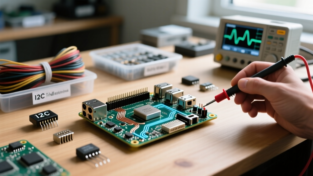
When your bus inevitably locks up, a structured debugging workflow is essential. The standard i2cdetect -y 1 command is your first line of defense. However, misinterpreting its output leads to wasted hours. If you see UU in the matrix, it does not mean the device is broken; it means a Linux kernel driver has already claimed that address (common with RTC modules like the DS3231). To free it, you must unbind the driver via sysfs before user-space Python scripts can access it.
The Broadcom Clock Stretching Bug
Critical Workflow Alert: The BCM2835 (Pi 3) and BCM2711 (Pi 4) SoCs contain a known silicon errata regarding I2C clock stretching. The hardware I2C master cannot reliably handle slaves that hold the SCL line low to request more processing time.
If you are interfacing the Pi with certain Arduinos acting as I2C slaves, or sensors like the Sensirion SHT31 that heavily utilize clock stretching, the Pi will drop bytes or freeze. The hardware workaround is to abandon the hardware I2C peripheral and instantiate a software-based I2C bus using the device tree overlay. Add dtoverlay=i2c-gpio,i2c_gpio_sda=23,i2c_gpio_scl=24 to your config.txt. This creates a new /dev/i2c-3 interface that is bit-banged via the CPU, perfectly honoring clock stretching delays and saving you from chasing phantom data corruption bugs.
By mastering baud rate tuning, respecting bus capacitance limits, leveraging multiplexers, and working around Broadcom silicon quirks, you transform the Raspberry Pi from a fragile I2C master into a robust, industrial-grade data acquisition hub.