
Critical Hardware Warning: Never apply power to a Semtech SX1276 or SX1262 LoRa module without an antenna connected. The resulting Voltage Standing Wave Ratio (VSWR) will reflect RF energy back into the power amplifier, permanently destroying the silicon in seconds.
Integrating Long Range (LoRa) transceivers with the Arduino ecosystem is a rite of passage for IoT makers and agricultural telemetry engineers. However, the journey from purchasing a raw Semtech breakout board to successfully transmitting a payload is fraught with hardware traps. Unlike simple I2C sensors, LoRa modules demand strict adherence to SPI bus timing, precise voltage logic translation, and chip-specific interrupt mapping. This comprehensive compatibility guide dissects the hardware and software realities of pairing LoRa modules with Arduino microcontrollers in 2026, ensuring your mesh networks deploy without silent failures.
The 3.3V Logic Trap: Voltage Compatibility
The most common point of failure in DIY LoRa projects is logic level mismatching. The vast majority of raw LoRa modules—including the ubiquitous HopeRF RFM95W (based on the SX1276) and modern SX1262 breakouts—are strictly 3.3V devices. Feeding 5V logic from a standard Arduino Uno R3 or Arduino Mega 2560 into the module's SPI pins will degrade the GPIO gates over time or cause immediate catastrophic failure.
Native 3.3V vs. 5V Tolerant Architectures
If you are designing a custom PCB or selecting a microcontroller for a new deployment, bypass the level-shifting headache entirely by choosing a native 3.3V Arduino-compatible board. The Arduino MKR WAN 1310, Adafruit Feather M0, and the Arduino Nano 33 IoT operate at 3.3V logic natively, allowing direct SPI connection to LoRa silicon.
For legacy 5V boards like the Uno or Mega, you must implement bidirectional logic level translation. Makers often reach for the TI TXB0108E bi-directional translator, but this is a critical error for SPI buses. The TXB0108E relies on auto-direction sensing that frequently conflicts with SPI clock edges, causing data corruption. Instead, use a CD4050B non-inverting buffer for the unidirectional lines (MOSI, SCK, NSS) and a discrete BSS138 MOSFET circuit for the bidirectional MISO line. Alternatively, purchase pre-regulated breakout boards from Adafruit or SparkFun that integrate these BSS138 translation circuits directly on the PCB.
Silicon Architecture: SX1276 vs SX1262
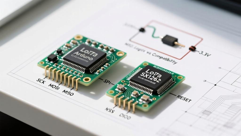
Understanding the underlying silicon is mandatory for software compatibility. The Arduino LoRa ecosystem is currently split between two primary Semtech chip families, each with distinct hardware requirements.
The Legacy Standard: SX127x (SX1276 / SX1278)
The SX1276 (868/915 MHz) and SX1278 (433 MHz) are the workhorses of the LoRaWAN ecosystem. Found on the Dragino LoRa Bee and HopeRF RFM95W, these chips are forgiving but power-hungry. They feature dedicated digital I/O pins (DIO0 through DIO5). For basic packet reception and transmission, the Arduino only needs to monitor DIO0, which triggers a hardware interrupt when a packet is fully transmitted or received.
The Modern Choice: SX126x (SX1262)
The SX1262 offers a massive leap in power efficiency (crucial for battery-operated soil sensors) and supports higher transmission power up to +22 dBm. However, its interrupt architecture is entirely different. The SX1262 multiplexes its interrupts internally. Instead of DIO0, the Arduino must monitor DIO1 for all primary packet and timeout events. If you wire an SX1262 using an SX1276 schematic, your Arduino will never receive the interrupt signal, and your code will hang indefinitely waiting for a payload.
SPI Pinout Mapping & Wiring Matrix
LoRa modules utilize the SPI protocol (Mode 0: CPOL=0, CPHA=0). While SPI pins are standardized on the microcontroller side, the Chip Select (NSS), Reset (RST), and Interrupt (DIO) pins are arbitrary and must be defined in your firmware. Below is the definitive wiring matrix for common Arduino form factors.
| Module Pin | Arduino Uno / Nano (ATmega328P) | Arduino Mega 2560 | Arduino MKR / Zero (SAMD21) |
|---|---|---|---|
| VCC | 3.3V (Do NOT use 5V) | 3.3V | 3.3V |
| GND | GND | GND | GND |
| SCK | Pin 13 | Pin 52 | SCK (ICSP or SPI Header) |
| MISO | Pin 12 | Pin 50 | MISO |
| MOSI | Pin 11 | Pin 51 | MOSI |
| NSS (CS) | Pin 10 (User Defined) | Pin 53 (User Defined) | Pin 7 (User Defined) |
| RST | Pin 9 | Pin 48 | Pin 6 |
| DIO0 / DIO1 | Pin 2 (Hardware Interrupt) | Pin 2 (Hardware Interrupt) | Pin 5 (External Interrupt) |
The Library Fragmentation Problem
Hardware compatibility is only half the battle; software abstraction layers dictate whether your project compiles or fails. The Arduino IDE hosts several LoRa libraries, but they are not universally compatible across chip families.
Why LoRa.h is Failing Modern Projects
For years, Sandeep Mistry's arduino-LoRa library was the gold standard. It is exceptionally well-documented and perfect for SX1276/SX1278 modules. However, it lacks support for the SX126x family, SX128x (2.4GHz), and advanced LoRaWAN MAC layer implementations. Attempting to force an SX1262 module to initialize using LoRa.begin() will result in an immediate failure, as the underlying SPI register maps are entirely different.
The RadioLib Standard
For any new project in 2026, Jan Gromeš's RadioLib GitHub Repository is the undisputed universal standard. RadioLib abstracts the silicon differences, allowing you to instantiate an SX1262 or SX1276 object with identical API calls. It also handles the complex DIO1 interrupt mapping automatically and provides granular control over SPI bus speeds, which is critical for debugging hardware faults.
Hardware Failure Modes & SPI Debugging
When your serial monitor outputs Init failed, code -2, you are facing a hardware communication breakdown. In RadioLib, error code -2 translates to ERR_CHIP_NOT_FOUND. The Arduino is attempting to read the silicon version register via SPI, but receiving garbage data or 0xFF. Here is how to systematically isolate the failure:
- Parasitic Capacitance on Breadboards: LoRa modules attempt to negotiate SPI clock speeds up to 8 MHz or 10 MHz. Standard solderless breadboards introduce severe parasitic capacitance on the MISO/MOSI lines, rounding off the square wave clock edges. Fix: Force the SPI clock down to 2 MHz using
SPI.setClockDivider(SPI_CLOCK_DIV4)or RadioLib'smodule.setSPIConfig()method. - Missing NSS Pull-Up Resistors: The SPI bus is shared. If the LoRa module's NSS (Chip Select) line floats during Arduino boot, the module may interpret random noise as SPI commands, locking its internal state machine. Fix: Solder a 10kΩ pull-up resistor between the NSS pin and 3.3V to ensure the module remains deselected until the Arduino explicitly pulls it LOW.
- Reset Pin Timing: The SX1262 requires a highly specific reset sequence: pull RST LOW for 10ms, release to HIGH, and wait exactly 20ms before initiating SPI. If your Arduino sketch rushes the SPI initialization before the internal voltage regulators stabilize, the chip will reject the handshake. Fix: Inject a
delay(50)immediately after releasing the reset pin in your setup routine.
By respecting the strict 3.3V logic requirements, mapping the correct DIO interrupt pins for your specific silicon generation, and utilizing modern abstraction libraries like RadioLib, you can transform a frustrating pile of jumper wires into a robust, kilometers-spanning IoT node. Always verify your SPI traces, respect the VSWR antenna rules, and let the silicon do the heavy lifting.
For further reading on hardware integration, review the Adafruit Feather M0 LoRa Guide, which provides excellent visual references for onboard level-shifting architectures.