
Every functional electrical system relies on a delicate, invisible balance between the flow of energy and the strict containment of that energy. When apprentices and safety engineers ask, what is an insulator in electricity, the answer goes far beyond a simple textbook definition. An insulator is the primary safety barrier that prevents catastrophic short circuits, ground faults, and lethal arc flashes. In the field, treating insulation as a passive, invincible wrapper is a fatal mistake. Insulation degrades, cracks, and fails under thermal, mechanical, and environmental stress.
This comprehensive safety guide explores the atomic mechanics of insulators, real-world material breakdown thresholds, and the critical field testing protocols required to maintain electrical safety in residential, commercial, and industrial environments.
The Core Definition: Containment and Isolation
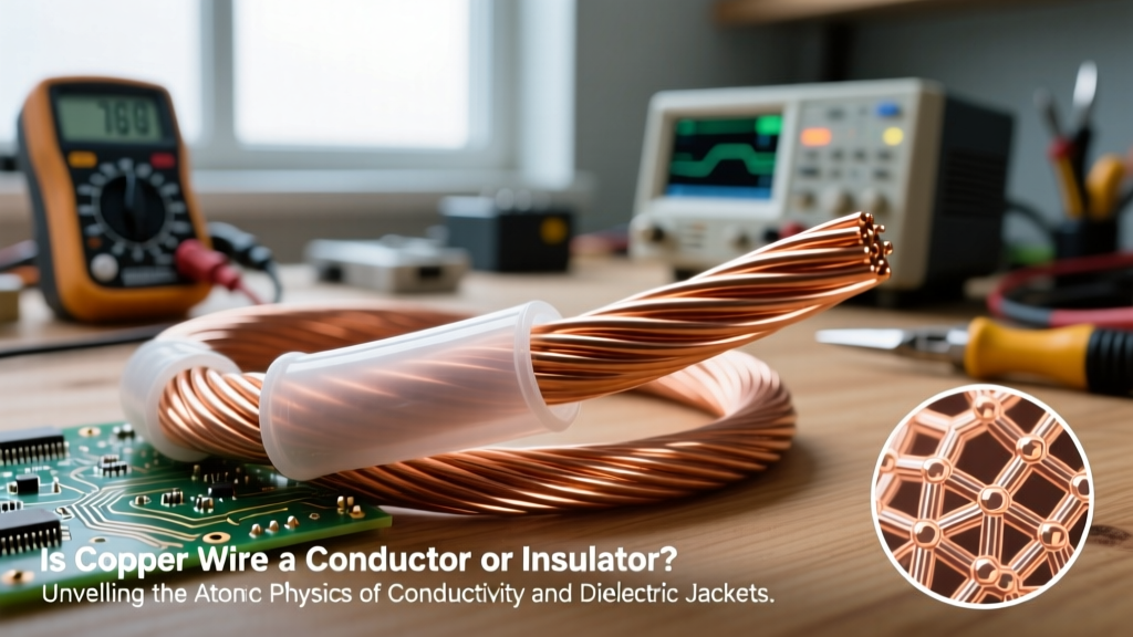
In electrical engineering, an insulator is a material whose internal atomic structure strongly resists the free flow of electric current. While conductors (like copper or aluminum) are chosen for their ability to move electrons efficiently, insulators are selected for their ability to trap electrons in place. By wrapping a conductive core in an insulating jacket, we force the electrical current to follow a designated path, preventing it from arcing to grounded surfaces, adjacent phases, or human operators.
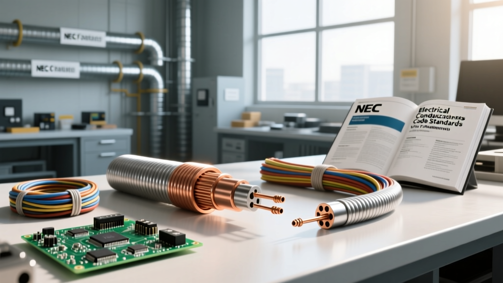
From a safety perspective, the insulation jacket is the first line of defense against shock and fire hazards. According to the NFPA 70 National Electrical Code (NEC), the selection and maintenance of wire insulation types (such as THHN, XHHW, or MI cable) are strictly regulated based on ambient temperature, moisture exposure, and voltage levels.
Atomic Anatomy: The Band Gap Explained
To truly understand insulation failure, you must look at the atomic level. The insulating properties of a material are dictated by its electronic band structure—specifically, the 'band gap' between the valence band (where electrons are bound to atoms) and the conduction band (where electrons can move freely).
- Conductors: Have overlapping valence and conduction bands, requiring virtually zero energy to move electrons.
- Semiconductors: Have a small band gap (typically 1-3 electron volts), allowing current flow under specific conditions.
- Insulators: Possess a massive band gap (typically greater than 5 electron volts). As detailed by Georgia State University's HyperPhysics database on band theory, the energy required to rip an electron from its covalent bond and push it into the conduction band is extraordinarily high.
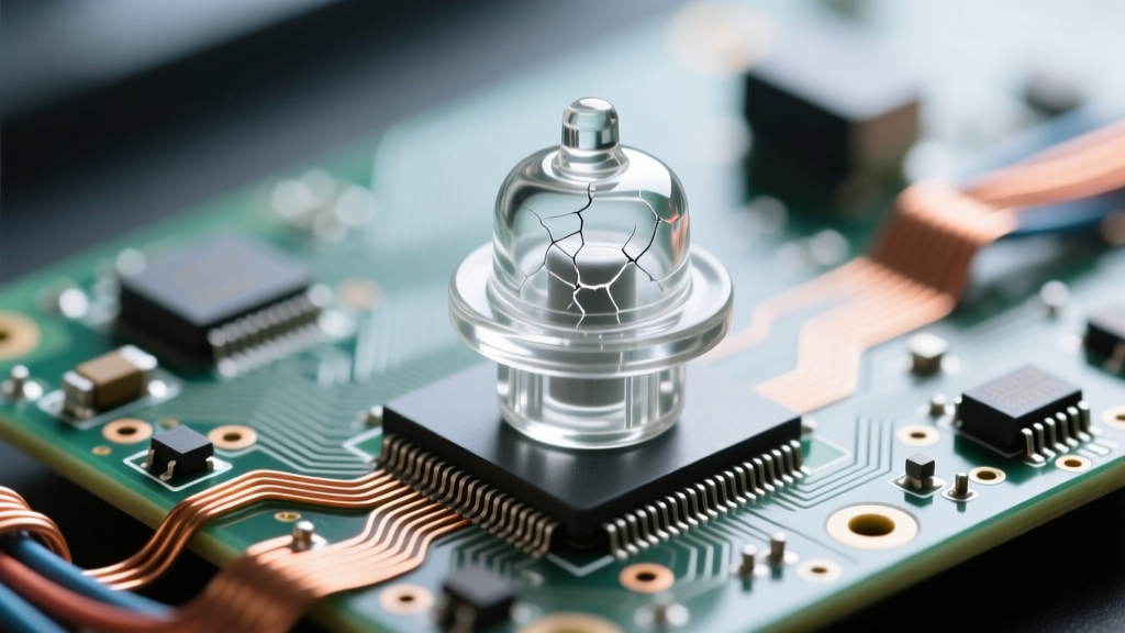
However, this band gap is not infinite. If the applied voltage exceeds the material's dielectric strength, the electric field will literally tear electrons from their atomic bonds, causing a violent, conductive puncture known as dielectric breakdown.
Dielectric Strength: Material Breakdown Thresholds
Dielectric strength is measured in kilovolts per millimeter (kV/mm) and represents the maximum electric field a material can withstand before it catastrophically fails and becomes conductive. Below is a comparison of common electrical insulating materials used in modern wiring and components.
| Insulating Material | Dielectric Strength (kV/mm) | Max Continuous Temp | Common Field Application |
|---|---|---|---|
| PVC (Polyvinyl Chloride) | 40 - 50 | 70°C to 105°C | Standard THHN/THWN-2 building wire, control cables |
| XLPE (Cross-Linked Polyethylene) | 50 - 70 | 90°C (250°C short-circuit) | Medium/High voltage underground distribution, XHHW-2 |
| PTFE (Teflon) | 60 - 100 | 260°C | Aerospace wiring, high-temp industrial sensor leads |
| EPR (Ethylene Propylene Rubber) | 30 - 40 | 90°C to 105°C | Flexible mining cables, marine shore power cords |
| Alumina Ceramic | 15 - 20 | 1000°C+ | High-voltage transmission line suspension insulators |
Safety Note: While PVC is ubiquitous in residential wiring, its dielectric strength plummets as temperatures approach 105°C. In high-ambient-temperature environments like attics or near industrial boilers, wire ampacity must be heavily derated to prevent the insulation from softening, thinning, and ultimately failing.
Critical Failure Modes: When Safety Barriers Collapse
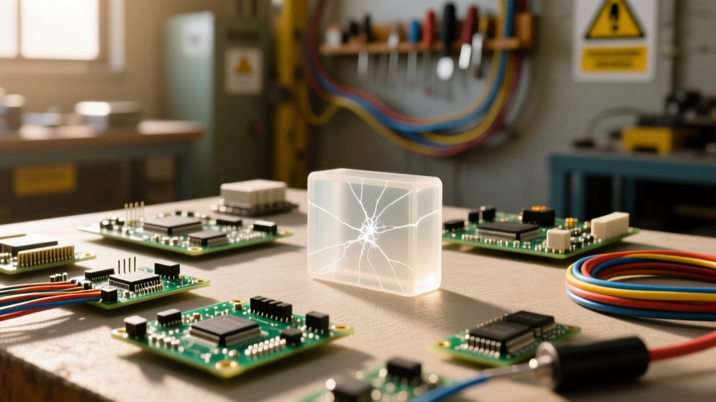
Insulators rarely fail instantly under normal operating voltages. Instead, they succumb to cumulative environmental and electrical stressors. Recognizing these failure modes is a core competency for any electrical safety inspector.
1. Thermal Tracking and Carbonization
When an insulator is exposed to localized overheating (often caused by a loose termination or high-resistance fault), the organic polymers in materials like PVC or rubber begin to degrade. This thermal degradation releases carbon. Because carbon is highly conductive, it forms microscopic, branching conductive paths across the surface of the insulator—a phenomenon known as 'electrical tracking.' Once a carbon track bridges the gap between a live conductor and ground, it triggers a massive short circuit and arc flash.
2. Corona Discharge and Ozone Degradation
In high-voltage systems (typically above 2000V), the electric field concentration at sharp edges or microscopic voids within the insulation can ionize the surrounding air. This creates a faint, hissing corona discharge. The ionization process generates ozone (O3), a highly reactive gas that rapidly attacks and cracks rubber and polymer-based insulators. If you detect a distinct 'bleach' or metallic odor near high-voltage switchgear, ozone is actively destroying the insulation.
3. Moisture Ingress and Hydrolysis
Water is a polar molecule and an excellent solvent for ionic impurities. When micro-cracks develop in an outdoor cable jacket, moisture wicks into the insulation via capillary action. Over time, this causes 'water treeing' in XLPE cables—microscopic, fern-like structures of water-filled voids that drastically reduce the dielectric strength of the cable, eventually leading to a subterranean fault.
Field Safety Protocols: Testing and Inspecting Insulation
Visual inspection is insufficient for verifying the integrity of an electrical insulator. A wire jacket may look perfectly intact while harboring severe internal dielectric weakness. To ensure safety before re-energizing a system, technicians must employ quantitative testing methods.
Insulation Resistance (Megger) Testing
The industry standard for verifying insulator health is the Insulation Resistance Test, performed using a megohmmeter (commonly called a Megger). This device applies a high-voltage DC potential to the conductor and measures the micro-amp leakage current flowing through the insulation to ground.
According to Fluke Corporation's guidelines on insulation resistance testing, standard field protocols dictate:
- Test Voltage: Apply 500V DC for equipment rated up to 600V AC. Apply 1000V DC for equipment rated up to 1000V AC.
- Minimum Acceptable Resistance: The NEC and NETA standards generally mandate a minimum of 1.0 Megohm per 1000 feet of conductor. However, modern, healthy XLPE or PVC wiring should read in the hundreds or thousands of Megohms.
- Polarization Index (PI):strong> For large motors and transformers, a 10-minute to 1-minute ratio (PI) is calculated to detect bulk moisture contamination within the winding insulation.
Infrared Thermography
Because failing insulation often precedes a short circuit with localized heat generation, infrared (IR) thermography is a vital non-contact safety tool. Scanning distribution panels under load can reveal 'hot spots' where insulation is thinning or where loose connections are generating enough thermal energy to melt the surrounding wire jackets.
Summary: Respect the Barrier
Understanding what is an insulator in electricity requires recognizing it as an active, vulnerable component of the electrical circuit. Whether you are pulling THHN through a hot conduit, terminating XHHW in a damp underground vault, or inspecting ceramic standoffs on a transmission tower, the insulator is the only thing standing between controlled energy and catastrophic failure. Adhere strictly to temperature derating tables, perform routine Megger testing, and never assume that a visually intact jacket guarantees dielectric integrity.