
Why Use the I2C Bus on Raspberry Pi for MCU Projects?
The Inter-Integrated Circuit (I2C) protocol remains the backbone of modern maker electronics. When building complex robotics, environmental monitoring stations, or automated test rigs, you often need the high-level processing power of a Raspberry Pi combined with the real-time, low-latency GPIO control of a microcontroller like an Arduino. The I2C bus on Raspberry Pi provides the perfect bridge for this architecture. Unlike UART, which requires dedicated TX/RX pairs for every device, or SPI, which demands individual chip select lines, I2C allows up to 127 devices to share just two wires: Serial Data (SDA) and Serial Clock (SCL).
However, interfacing a Linux-based single-board computer with bare-metal microcontrollers introduces specific hardware and software challenges. From logic level mismatches to clock stretching bugs, mastering the i2c bus raspberry pi ecosystem requires a deep understanding of both the silicon and the operating system. This comprehensive guide will walk you through hardware wiring, OS configuration, Python-to-Arduino bridging, and advanced troubleshooting.
Hardware Anatomy: Pi GPIO to I2C Pin Mapping
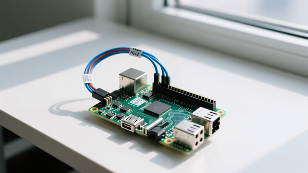
Before writing a single line of code, we must address the physical layer. The primary I2C bus (I2C1) on the Raspberry Pi 4B and Pi 5 is mapped to specific pins on the 40-pin header:
- SDA (Serial Data): GPIO 2 (Physical Pin 3)
- SCL (Serial Clock): GPIO 3 (Physical Pin 5)
According to the Raspberry Pi Official Documentation, the primary I2C bus features onboard 1.8kΩ pull-up resistors tied to the 3.3V power rail. While 4.7kΩ is the standard pull-up value for most 100kHz I2C networks, the Pi's stronger 1.8kΩ pull-ups are designed to ensure fast rise times on the relatively high-capacitance GPIO traces. However, this means you must be exceptionally careful when adding external modules that also contain pull-up resistors, as paralleling them can pull the resistance too low, causing excessive current draw and signal degradation.
The 3.3V vs 5V Logic Level Trap
This is the most common point of failure for beginners. The Raspberry Pi operates strictly at 3.3V logic. Feeding 5V from an Arduino Uno's SDA/SCL lines directly into the Pi's GPIO pins will likely destroy the Pi's SoC over time, or instantly if the voltage spikes.
The Solution: You must use a bi-directional logic level shifter. The SparkFun I2C Tutorial highly recommends MOSFET-based level shifters (like those using the BSS138 transistor or the Texas Instruments PCA9306 chip). These safely translate the 5V Arduino signals down to 3.3V for the Pi, and vice versa, without the propagation delays inherent in simple voltage divider circuits.
Step-by-Step: Enabling the I2C Interface
By default, the I2C kernel module is disabled in Raspberry Pi OS to save resources and prevent pin conflicts. Follow these steps to enable it:
- Open the terminal and launch the configuration tool:
sudo raspi-config - Navigate to Interface Options > I2C and select Yes to enable the ARM I2C interface.
- Reboot your Pi:
sudo reboot - Install the essential user-space tools and Python libraries:
sudo apt-get update
sudo apt-get install i2c-tools python3-smbus python3-pip
pip3 install smbus2
The i2c-tools package provides the vital i2cdetect utility, while smbus2 is the modern, actively maintained Python library for I2C communication, replacing the legacy smbus package.
Detecting Devices: Using i2cdetect
Once your hardware is wired through a level shifter and the software is configured, verify the connection. Run the following command to scan the primary bus:
i2cdetect -y 1The -y flag disables interactive mode, and 1 specifies the I2C bus number (Bus 1 is the primary GPIO bus). If your Arduino or sensor is connected correctly, you will see its hexadecimal address populate in the grid (e.g., 08 or 76). If the grid is entirely empty, check your wiring, ensure the level shifter is powered on both the LV (3.3V) and HV (5V) sides, and verify that the slave device is actually programmed to listen.
Practical Tutorial: Raspberry Pi to Arduino I2C Bridge
Let us build a practical bridge where the Raspberry Pi acts as the I2C Master, requesting sensor data from an Arduino acting as the I2C Slave. This architecture is ideal for offloading real-time PWM motor control or high-speed ADC sampling to the MCU while the Pi handles network logging and UI dashboards.
Arduino Sketch (The Slave)
Using the Arduino Wire Library, we configure the Arduino to listen on address 0x08. We will use an interrupt service routine (ISR) approach to handle requests without blocking the main loop.
#include <Wire.h>

// Simulated sensor data
int sensorValue = 42;

void setup() {
  Wire.begin(0x08);                // Join I2C bus with address 0x08
  Wire.onRequest(requestEvent);    // Register request event handler
  Serial.begin(115200);
}

void loop() {
  // Main loop remains free for real-time MCU tasks
  sensorValue = analogRead(A0);    // Read actual sensor
  delay(10);
}

// Function that executes whenever data is requested by master
void requestEvent() {
  // Send 2 bytes (integer) to the Pi
  Wire.write(highByte(sensorValue));
  Wire.write(lowByte(sensorValue));
}
Python Script (The Master)
On the Raspberry Pi, we use smbus2 to request those two bytes and reconstruct the integer.
import smbus2
import time

# I2C bus 1 on Raspberry Pi
bus = smbus2.SMBus(1)
ARDUINO_ADDR = 0x08

def read_sensor():
    try:
        # Read 2 bytes from the Arduino
        data = bus.read_i2c_block_data(ARDUINO_ADDR, 0, 2)
        # Reconstruct the 16-bit integer
        value = (data[0] << 8) | data[1]
        return value
    except OSError as e:
        print(f'I2C Communication Error: {e}')
        return None

while True:
    val = read_sensor()
    if val is not None:
        print(f'Sensor Reading: {val}')
    time.sleep(1)
Troubleshooting Matrix: IO Errors and Hardware Faults
Working with the I2C bus on Raspberry Pi often yields cryptic OSError: [Errno 121] Remote I/O error messages. Use this matrix to diagnose the root cause rapidly.
| Symptom / Error Code | Root Cause Analysis | Hardware / Software Fix |
|---|---|---|
Errno 121 Remote I/O Error |
The Pi sent a clock pulse but received no ACKnowledge (ACK) bit from the slave. The slave is either unpowered, on the wrong address, or missing a common ground. | Verify GND connection between Pi, Level Shifter, and Arduino. Run i2cdetect -y 1 to confirm address. |
Errno 110 Connection Timed Out |
Clock Stretching issue. The Arduino is holding the SCL line low too long, causing the Pi's hardware I2C controller to timeout. | Reduce I2C baud rate in /boot/config.txt by adding dtparam=i2c_baudrate=10000. Alternatively, use software I2C (bit-banging). |
| Garbage Data / Random Values | Signal integrity degradation due to excessive bus capacitance or missing pull-up resistors on the 5V side of the level shifter. | Ensure the HV side of the level shifter has 4.7kΩ pull-ups to 5V. Keep I2C wires under 30cm (1 foot). |
| Pi GPIO Pin Overheating | 5V logic backfeeding into the 3.3V Pi GPIO due to a missing or blown level shifter. | Immediately disconnect power. Replace the level shifter and verify Pi SoC functionality. |
Advanced Considerations: Clock Stretching and Multiplexing
One of the most notorious quirks of the Broadcom BCM2711 (Pi 4) and BCM2712 (Pi 5) SoCs is their handling of I2C Clock Stretching. Clock stretching occurs when a slave device (like an Arduino performing a heavy calculation or a slow ADC chip) needs more time to process data, so it physically holds the SCL line LOW to pause the master. The Raspberry Pi's hardware I2C controller has a known silicon bug where it fails to properly detect the stretched clock, resulting in corrupted data or dropped packets.
The Workaround: If your MCU project relies heavily on clock stretching, you have two options:
- Software I2C (Bit-Banging): Use the
i2c-gpiooverlay in the Pi'sconfig.txtto map I2C to standard GPIO pins handled by software. Software I2C handles clock stretching perfectly, albeit at lower maximum speeds. - Pre-stretch Buffering: Program your Arduino to read sensors in the background
loop()and instantly serve cached data via theWire.onRequest()ISR, ensuring the ISR executes in microseconds and requires no clock stretching.
Finally, if your project requires multiple identical sensors with the same hardcoded I2C address (e.g., three BME280 environmental sensors), utilize an I2C Multiplexer like the PCA9548A. This chip sits on the primary Pi I2C bus and acts as a switch, routing the SDA/SCL signals to one of eight downstream sub-buses, effectively eliminating address collisions and isolating bus capacitance.