
Whether you are sourcing components for a high-fidelity audio mixer, designing a custom analog synthesizer, or procuring replacement parts for industrial equipment, buying potentiometers in bulk carries inherent risks. Surplus bins, unauthorized distributors, and even direct factory batches can suffer from degraded carbon tracks, mechanical misalignments, or incorrect tapers. Knowing how to test a potentiometer is not just a troubleshooting skill; it is a critical quality assurance protocol for any serious hardware engineer or DIY builder.
This buyer’s verification guide will walk you through the exact methodologies to validate total resistance, taper accuracy, and Contact Resistance Variation (CRV) before you solder a single leg to your PCB.
The Hidden Risks of Bulk Potentiometer Sourcing
When procuring components like the Alps Alpine RK097 series for audio applications or the Bourns 3852 precision cermet trimmers, visual inspection is entirely insufficient. Counterfeit components often use cheap carbon composition elements instead of the specified conductive plastic or cermet, leading to rapid thermal drift and severe track noise.
Furthermore, improper storage in high-humidity environments can oxidize the wiper contacts. If you integrate these degraded components into a final product, you will face catastrophic field failures, manifesting as scratchy audio, dead spots in sensor arrays, or unstable voltage references. Implementing a strict incoming inspection protocol using the tests below ensures your bill of materials (BOM) matches reality.
Core Specifications to Verify Before and After Purchase
Before reaching for your multimeter, cross-reference the manufacturer’s datasheet. The following table outlines the primary parameters you must validate during your incoming quality control (IQC) checks.
| Parameter | Description | Acceptable Tolerance / Limit | Test Equipment Required |
|---|---|---|---|
| Total Resistance | Resistance between the two outer terminals. | ±10% to ±20% (Standard), ±5% (Precision) | Digital Multimeter (DMM) |
| Taper (Linearity) | The curve of resistance change relative to shaft rotation. | Independent Linearity: ±1% to ±5% | DMM + Rotation Jig |
| CRV (Contact Resistance Variation) | Dynamic noise generated by the wiper moving across the track. | < 2Ω (Conductive Plastic), < 10Ω (Carbon) | Oscilloscope or CRV Meter |
| Insulation Resistance | Isolation between the resistive element and the metal housing. | > 100 MΩ at 500VDC | Megohmmeter |
Step-by-Step: How to Test a Potentiometer with a Multimeter
A high-quality digital multimeter (DMM) like the Fluke 87V or Keysight U1252B is your first line of defense. Here is the systematic approach to component validation.
Test 1: Total Resistance and Tolerance
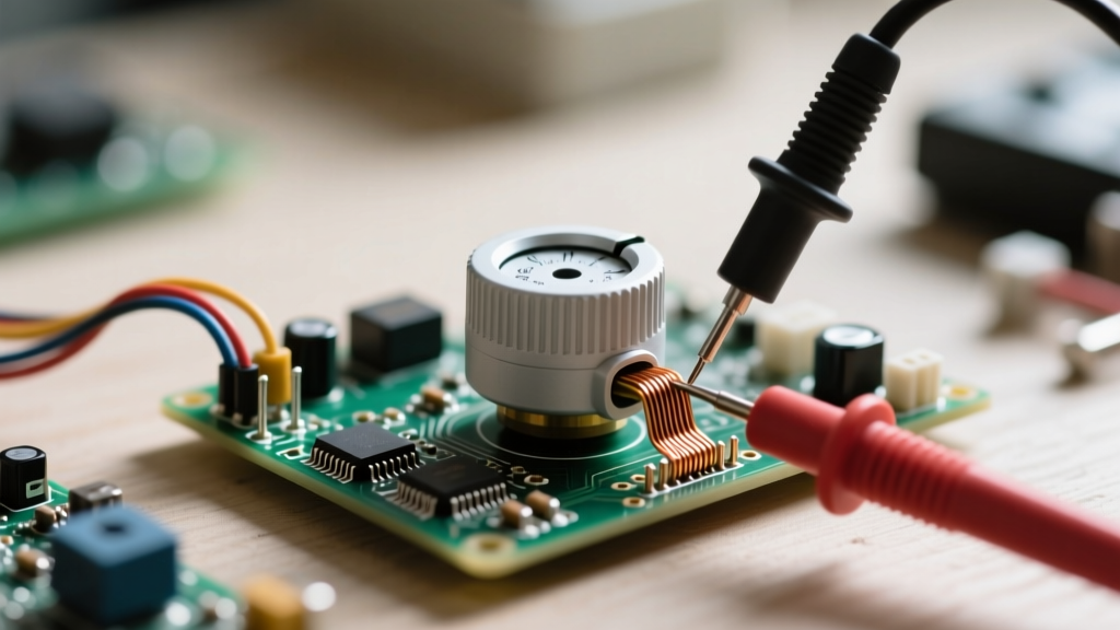
Set your DMM to the appropriate ohms range. Connect the probes to Terminal 1 (CCW) and Terminal 3 (CW). The wiper (Terminal 2) should be ignored for this specific measurement.
If you are testing a batch of Vishay P11A series 10kΩ potentiometers, your reading should fall strictly between 9.0kΩ and 11.0kΩ (assuming a standard ±10% tolerance). Readings that fluctuate wildly when you gently tap the component housing indicate internal structural weaknesses or loose terminal rivets.
Test 2: Verifying the Taper (Linear vs. Logarithmic)
Mislabelled tapers are a common issue with unbranded components. To verify the taper, you must measure the wiper’s resistance at specific mechanical intervals.
- Linear Taper (B-Taper): Connect the DMM between Terminal 1 and Terminal 2 (Wiper). Rotate the shaft to the exact mechanical center (50% rotation). The reading should be exactly 50% of the total resistance (e.g., 5.0kΩ on a 10kΩ pot).
- Logarithmic / Audio Taper (A-Taper): At 50% mechanical rotation, the resistance between the CCW terminal and the wiper should be significantly lower than the CW terminal. For a standard 10kΩ audio pot, you will typically measure approximately 1.0kΩ to 1.5kΩ on the CCW side, and 8.5kΩ to 9.0kΩ on the CW side at the midpoint.
Pro Tip: If you are testing reverse-log (C-Taper) pots for specialized panning circuits, the 50% rotation values will be inverted compared to the standard audio taper.
Test 3: Contact Resistance Variation (CRV) and Track Noise
CRV is the measure of dynamic noise. While a DMM is not fast enough to capture microsecond dropouts, you can perform a macro-level sweep test.
- Connect your DMM probes to the wiper and one outer terminal.
- Set the meter to measure minimum/maximum resistance or use a fast-logging mode.
- Slowly rotate the shaft through its entire mechanical travel.
For a premium conductive plastic potentiometer, the resistance should increase smoothly. If your DMM display shows sudden, massive jumps in resistance (e.g., spiking from 2.5kΩ to infinite/open-loop for a fraction of a second), the carbon track has a physical defect, or the wiper tension spring has failed. Reject the component immediately.
Advanced Verification: Oscilloscope Testing for Audio
For high-end audio applications, a multimeter is insufficient. You must visualize the track noise. This is how professional audio manufacturers test pots before installing them in mixing consoles.
The AC Injection Method: Inject a clean 1 kHz sine wave (1V peak-to-peak) across the outer terminals (1 and 3). Connect your oscilloscope probe to the wiper (Terminal 2). As you sweep the shaft slowly, the amplitude of the sine wave on the scope will increase or decrease. Any ‘steps’, flat-topping, or high-frequency fuzz superimposed on the sine wave indicates severe track degradation or wiper bounce.
This method instantly reveals Equivalent Noise Resistance (ENR) issues that a standard DMM sweep will completely miss. If you are building a boutique guitar pedal or a studio preamp, this oscilloscope test is mandatory for selecting the right batch of components.
Red Flags: When to Reject a Batch or Return a Component
During your selection and verification process, watch for these critical failure modes. If more than 2% of your bulk batch exhibits these traits, return the entire lot to the distributor:
- Mechanical Wobble: The shaft should not exhibit lateral play. Wobble causes inconsistent wiper pressure, leading to premature track wear.
- Non-Standard Rotational Torque: High-quality pots use specialized damping greases. If the shaft feels ‘gritty’ or requires vastly different torque to turn CW versus CCW, the internal lubrication has dried out or contaminated.
- Terminal Oxidation: Inspect the solder lugs or PCB pins under magnification. Yellowing or white crust on the pins indicates long-term improper storage, which will result in cold solder joints during your wave soldering or hand-soldering processes.
Recommended Test Gear for the Component Workbench
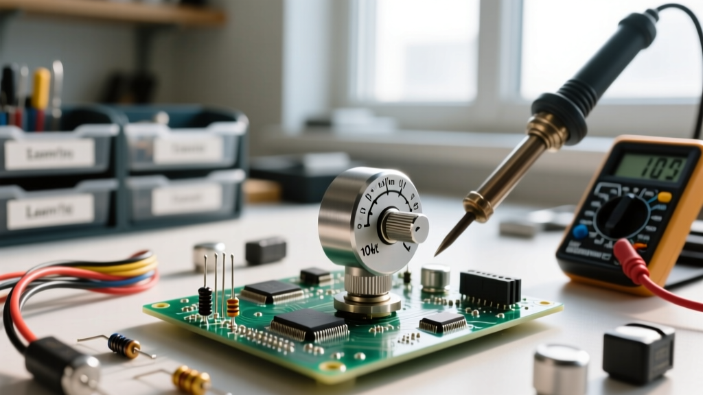
To execute these selection and verification protocols efficiently, equip your workbench with the following tools:
- Fluke 87V Industrial Multimeter: Features a fast continuity and min/max mode essential for catching macro-level dead spots during wiper sweeps.
- Rigol DS1054Z Oscilloscope: An affordable, high-value scope perfect for the 1 kHz AC injection test to visualize audio taper smoothness.
- Custom Rotary Test Jig: For bulk testing, 3D print a fixture that holds the pot body securely while a stepper motor rotates the shaft at a constant RPM, feeding wiper data to a microcontroller for automated CRV logging.
Ultimately, knowing how to test a potentiometer thoroughly bridges the gap between a datasheet promise and real-world performance. By integrating these verification steps into your purchasing workflow, you guarantee that every knob twist, fader slide, and sensor calibration in your final design operates with absolute precision.